The method of controlling the thickness of the protective layer on the surface of the steel mesh of the floor slab and the mold used

A technology of protective layer thickness and steel mesh, which is applied in the field of building slab pouring, can solve problems such as stirrup tilt, processing error, and uneven upper steel mesh, so as to reduce pouring errors, reduce pouring costs, and improve construction quality.

Active Publication Date: 2016-08-10
THE THIRD CONSTR & ENG OF CCFED
View PDF10 Cites 0 Cited by
  • Summary
  • Abstract
  • Description
  • Claims
  • Application Information

AI Technical Summary

Problems solved by technology

[0004] In the construction process of the prior art, it is difficult to ensure that the stirrups at the bottom of the upper steel mesh are all vertical, and some stirrups will tilt during the welding or binding process, resulting in insufficient height of the upper steel mesh; There will be processing errors, and sometimes inaccurate welding or binding points will cause the upper steel mesh to be uneven, causing the upper steel mesh to be high in some places and low in some places. Therefore, the poured floor will appear when the thickness of the floor is ensured. The distance between the upper steel mesh and the floor surface is also thick in some places and thin in some places, which affects the quality of the floor slab
It is not conducive to controlling the thickness of steel cover δ
During the pouring process, only the total thickness control of the floor slab is often paid attention to, while the thickness δ of the steel protective layer is ignored, which affects the construction quality of the floor slab

Method used


Image

  • The method of controlling the thickness of the protective layer on the surface of the steel mesh of the floor slab and the mold used
  • The method of controlling the thickness of the protective layer on the surface of the steel mesh of the floor slab and the mold used
  • The method of controlling the thickness of the protective layer on the surface of the steel mesh of the floor slab and the mold used

Examples


Embodiment

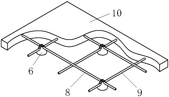
[0024] The thickness B of the slab in this example is 100±5mm, and the diameter D of the reinforcing steel mesh of the upper layer is 10mm. Concretely implement the construction according to the following steps:

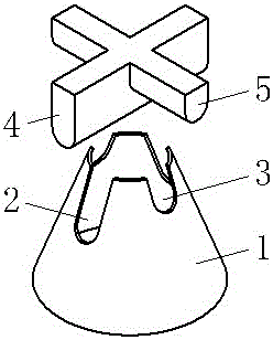
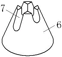
[0025] 1. Make the shaped concrete mold first. The shaped concrete mold comprises a conical cylinder 1 and a cross die made of 2mm steel plates. The upper hole diameter of the cone 1 is 50mm, the lower hole diameter is 120mm, and the height of the cone 1 is 95mm. The upper opening of the conical cylinder 1 is provided with four notches evenly distributed along the circumference, and the bottom of the notches is an arc. One pair of opposite notches is the deep notch 2, and the other pair of opposite notches is the shallow notch 3. The deep notch 2 has a depth equal to 25 and the shallow notch 3 has a depth equal to 15. The cross die includes vertically intersecting deep groove bead 4 and shallow groove bead 5 . The length of deep groove bead 4 and shallow groove ...


PUM

PropertyMeasurementUnit
thicknessaaaaaaaaaa
heightaaaaaaaaaa

Abstract

The invention discloses a method for controlling the thickness of a protection layer on the surface of a floor slab reinforcing mesh and a mould used in the method. According to the method, shaped concrete is used for replacing an existing reinforcing steel bar stirrup or used as a supplement of the reinforcing steel bar for supporting an upper-layer reinforcing mesh in a floor slab so that the flatness of the upper-layer reinforcing mesh in the floor slab is ensured, and thus the construction quality of the floor slab is improved; and the height h of the shaped concrete is less than the thickness B of the floor slab, a cross recess is formed in the top of the shaped concrete, the upper-layer reinforcing mesh in the floor slab is clamped in the cross recess in the top of the shaped concrete and then the floor slab is formed by pouring. According to the method, the problem of unflatness or inaccurate height location of the upper-layer reinforcing mesh due to the inclination of the door-shaped reinforcing steel bar stirrup in the prior art can not be caused, a construction operator can be helped to strictly control the thickness delta of the reinforcing steel bar protection layer of the upper-layer reinforcing mesh of the floor slab, the pouring error of the upper-layer reinforcing mesh and the plane of the floor slab is reduced, and the construction quality of pouring of the floor slab is improved. The consumption of reinforcing steel bars in the floor slab can also be reduced, and the pouring cost of the floor slab is lowered.

Description

technical field [0001] The invention relates to a method for controlling the thickness of a protective layer on the surface of a floor slab reinforcement mesh and a used mold, belonging to the technical field of building floor pouring. Background technique [0002] With the development of the construction industry, there are more and more high-rise buildings. Government departments, construction units, construction units, etc. have put forward higher requirements for the construction quality of the project, and formulated various related systems to increase the quality of project construction. The inspection strength not only raises higher requirements for the thickness of the floor slab, but also puts forward higher requirements for the distance between the steel mesh in the floor and the surface of the floor (that is, the thickness δ of the steel bar cover). [0003] In the traditional floor construction, after the floor formwork is supported, the lower steel mesh is woven...

Claims


Application Information

Patent Timeline
Patent Type & Authority Patents(China)
IPC IPC(8): E04C5/20E04G21/12
Inventor 杨广海吴坤钟佳蒋祥春
Owner THE THIRD CONSTR & ENG OF CCFED
Why Eureka
Try Eureka