Boiler induced-draft fan soot blower

A technology of soot blowing device and induced draft fan, which is applied to induced draft, components of pumping device for elastic fluid, mechanical equipment, etc., can solve problems such as unsatisfactory effect, loose ground bolts, equipment damage, etc.

Inactive Publication Date: 2013-09-11
章世斌
View PDF5 Cites 2 Cited by
  • Summary
  • Abstract
  • Description
  • Claims
  • Application Information

AI Technical Summary

Problems solved by technology

[0003] Boiler flue gas contains water vapor, sulfide and dust not completely removed by the dust collector. These substances condense and mix with dust to form mortar, which easily adheres to the blades of the induced draft fan, and most of them are bonded to the blades of the induced draft fan. On the non-working surface and the front and rear plates of the impeller, after the water evaporates, a relatively hard ash shell is formed and gradually deposits and thickens. When the ash deposit reaches a certain quality, part of the ash will fall off under the combined action of its own weight and rotating centrifugal force, and the fan rotor will The balance is destroyed and vibration is generated. When the vibration exceeds the specified value, it is necessary to stop the machine for manual cleaning, which will cause the boiler to be forced to press the fire to stop the furnace. Corner bolts loosened causing serious damage to equipment
[0004] If the induced draft fan is frequently stopped to clean up the dust accumulation, it will greatly affect the safe operation of the boiler and the stability of production. The soot on the blades can be removed by just pressing down on t

Method used


Image

  • Boiler induced-draft fan soot blower
  • Boiler induced-draft fan soot blower
  • Boiler induced-draft fan soot blower

Examples


Embodiment Construction

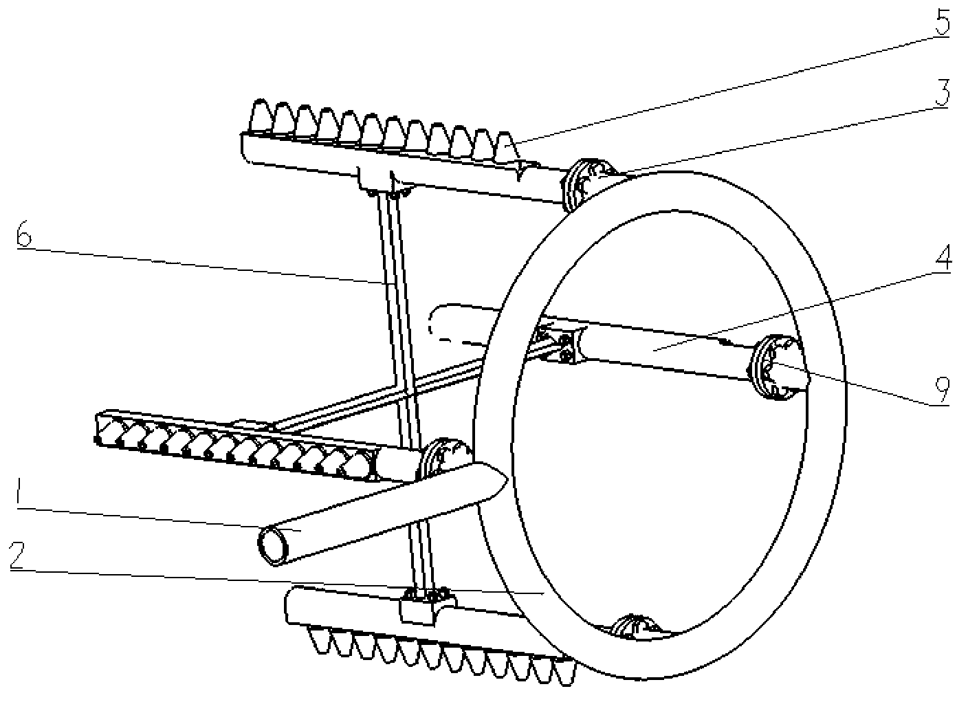
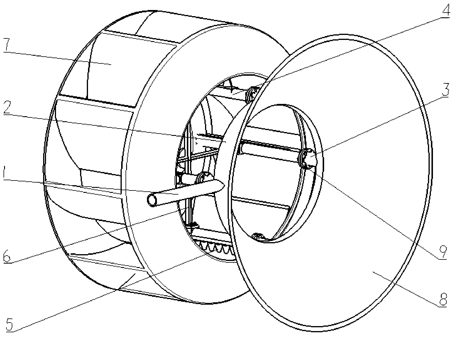
[0024] Attached below figure 1 , attached figure 2 And attached Figure 5 The working process of a boiler induced draft fan soot blowing device of the present invention is further described in detail through specific embodiments:

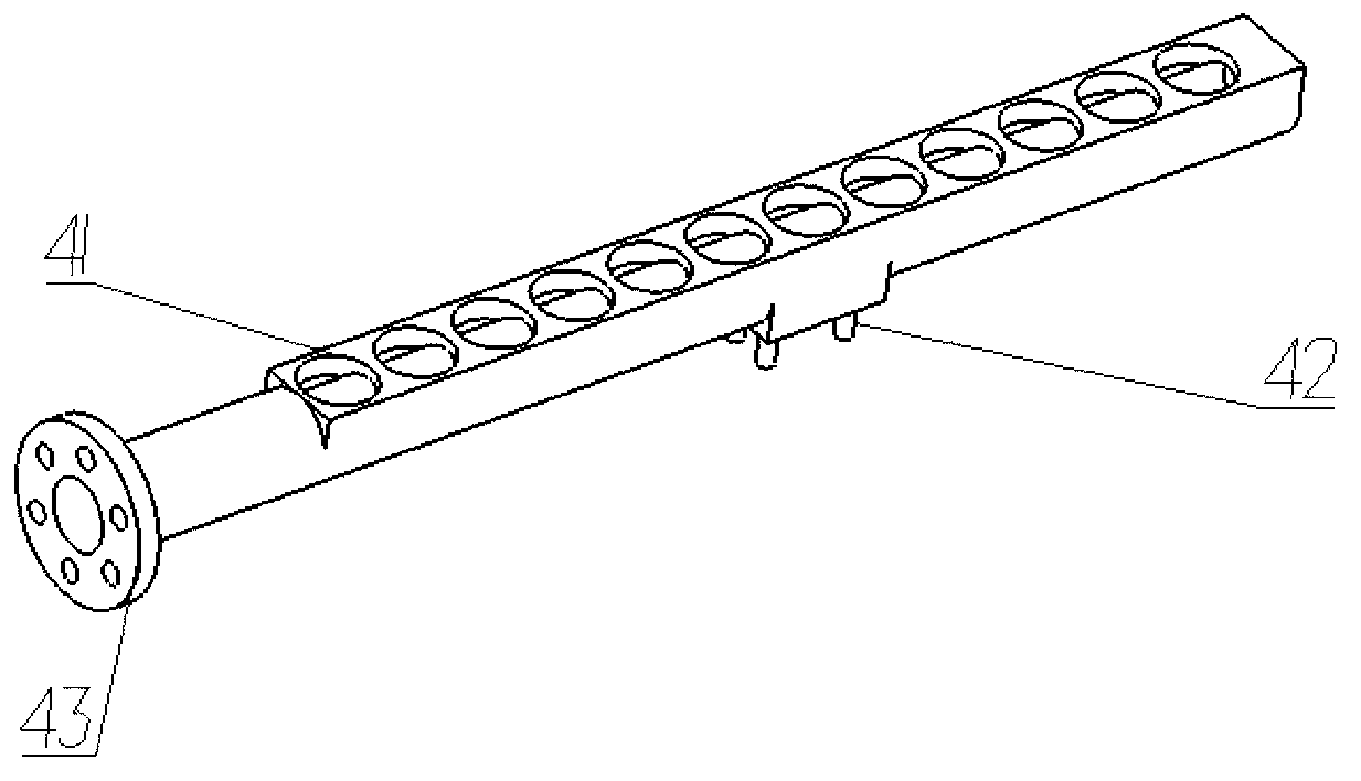
[0025] The high-pressure steam or air enters the air distribution pipe 2 through the inlet pipe 1, distributes the high-pressure steam or air to 4 or 2 outlet pipes through the air distribution pipe, and then enters the nozzle pipe. A row of tapered nozzles 5 is installed on the side of the nozzle pipe. Facing the impeller of the induced draft fan and keeping an appropriate distance from the blades of the impeller, the high-pressure steam or air is blown out after being accelerated through the tapered nozzle 5, and directly impacts on the inner side of the blade of the induced draft fan impeller 7, and the impeller 7 of the induced draft fan is blown out by the strong air flow. The dust on the blades is blown away; the nozzle pipe 4 is equipped w...


PUM


Abstract

The invention discloses a boiler induced-draft fan soot blower which is composed of an air inlet (1), air distribution pipes (2), an air outlet pipe (3), a nozzle pipe (4), a nozzle (5) and a supporting frame (6). The air distribution pipes (2) are ring-shaped and are arranged on a round contracted port of a current collector (8), the air nozzle pipes (4) are arranged symmetrically, the nozzle (5) is a gradually-contracted nozzle and is installed with an outlet (41) through threads in a matched mode, and the supporting frame (6) is fixedly connected with the nozzle pipe (4) through bolts (42) to play the role in fixing the nozzle pipe (4). The boiler induced-draft fan soot blower blows air to remove dust in the radial direction from the center of the impeller of the induced draft fan, counter-acting force of air flow inside the nozzle are mutually cancelled, and under the fixing function of the supporting frame, stability and effectiveness of working of the soot blower are ensured. The boiler induced-draft fan soot blower can use air or steam to carry out dust blowing, is simple in part structure, and convenient to process and produce and assemble in batch.

Description

technical field [0001] The invention relates to a boiler induced draft fan device, in particular to a boiler induced draft fan soot blowing device. Background technique [0002] The boiler induced draft fan is one of the necessary equipment to ensure the normal operation of the boiler. Once the induced draft fan stops running, it will directly affect the normal operation and output of the boiler. Therefore, ensuring the normal operation of the boiler induced draft fan is one of the necessary conditions to ensure the normal operation of the boiler. At present An important factor affecting the normal operation of the induced draft fan of the boiler is the vibration problem caused by the dust accumulation on the blades of the induced draft fan. [0003] Boiler flue gas contains water vapor, sulfide and dust not completely removed by the dust collector. These substances condense and mix with dust to form mortar, which easily adheres to the blades of the induced draft fan, and mo...

Claims


Application Information

Patent Timeline
IPC IPC(8): F04D29/70F23L17/00
Inventor 章世斌蒋庆群张贵良康世华苏元强高冀平王建磊王鹏张江
Owner 章世斌
Why Eureka
Try Eureka