Multi-substrate combining detection method based on laser measurement

A detection method and laser measurement technology, applied in the field of testing, can solve problems such as inability to adjust, large measurement error, difficult measurement, etc., and achieve the effects of convenient translation and rotation, improved measurement accuracy, and direct presentation method.

Active Publication Date: 2013-09-11
XIAN AIRCRAFT DESIGN INST OF AVIATION IND OF CHINA
View PDF5 Cites 20 Cited by
  • Summary
  • Abstract
  • Description
  • Claims
  • Application Information

AI Technical Summary

Problems solved by technology

[0008] The disadvantages of method 1 and method 2 are: they cannot be adjusted under the guidance of the adjustment amount; the measurement error is large; the operation is cumbersome; the labor intensity is high; the efficiency is low
For a large base surface, it is necessary to make a judgment through repeated adjustments and observations, which is

Method used


Image

  • Multi-substrate combining detection method based on laser measurement
  • Multi-substrate combining detection method based on laser measurement

Examples


Example Embodiment

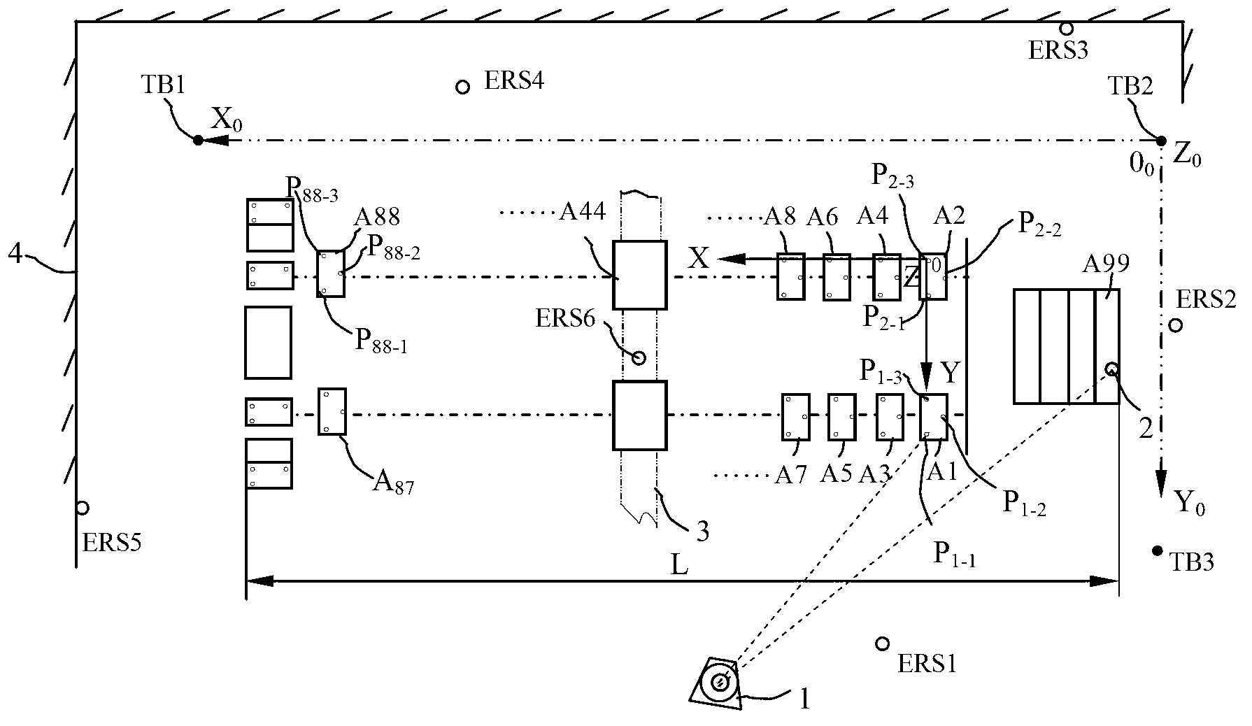
[0039] Example 1: figure 1 Shown: substrate [A1], ... [A99]; laser tracker [1]; target ball [2]; substrate mounting support frame [3]; wall [4]. Combine and test the horizontal datum of a certain main structure. The target body length L is 40m, which is composed of 99 substrates. Set up the LTD500 laser tracker [1] at the measuring station, and the static coordinate accuracy (2δ) of the laser tracker is ±10μm / m. Pre-lay the qualified substrate [A1] to the substrate [A99] on the substrate support frame. The substrates are distributed in two rows of odd and even. It is agreed that the positioning holes on the substrate are numbered in counterclockwise order. The three positioning holes on the substrate [A1] Number is P 1-1 , P 1-2 , P 1-3 , Determine the target offset and the coordinate origin position, use the CATIA software to obtain the theoretical coordinates with the target ball center offset on the digital model, and import the theoretical coordinates into the application ...

Example

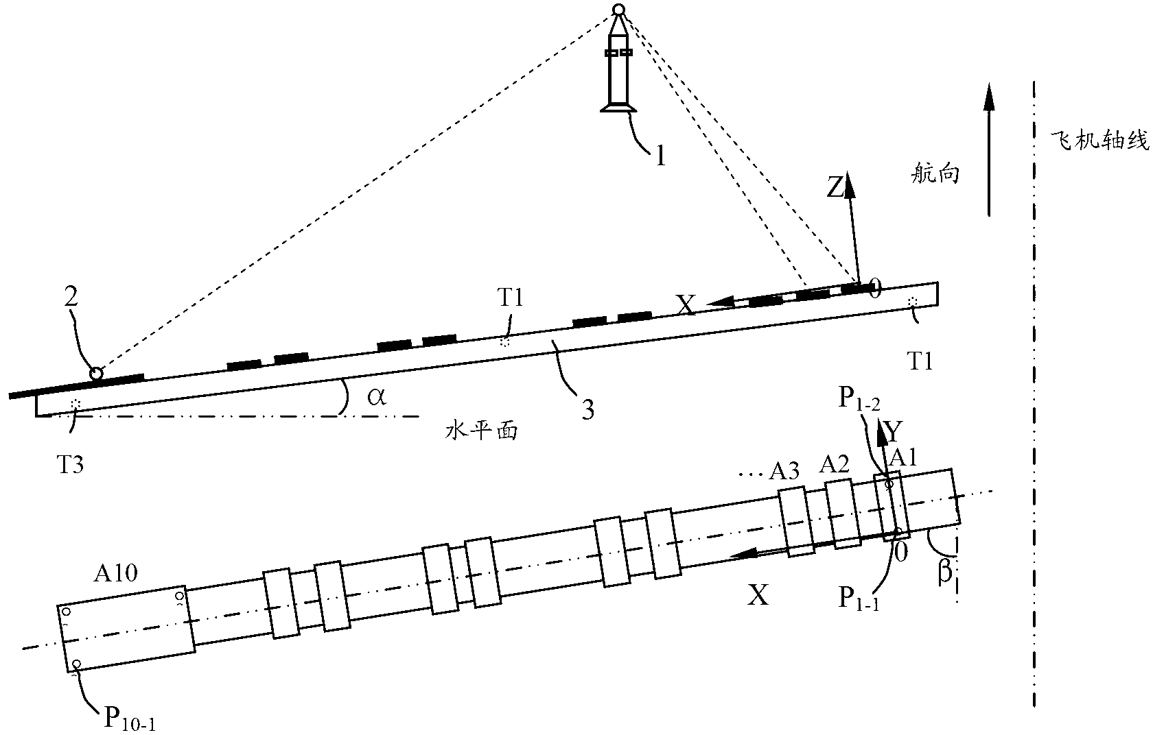
[0040] Example 2: figure 2 Shown: substrate [A1]......[A10]; laser tracker [1]; target ball [2], substrate mounting support frame [3]. Split the installation datum plane of a certain aircraft wing control test bench. The characteristic of the plane to be measured is that the reference plane has a compound angle relationship with each axis of the aircraft coordinate system. Therefore, it is necessary to use the laser tracker to first install and debug the downturn angle and the sweep angle of the installation surface of the platform under the aircraft coordinate system, and then solve the installation flatness problem. The specific implementation is as follows:

[0041] Set up the laser tracker [1] on the wing root end of the wing control test bench so that the laser beam emitted can be directly projected to the surface of the object to be measured. Measure P in the aircraft coordinate system 1-1 , P 1-2 , P 10-1 In the same way, measure the three points T1 where the substrate...


PUM


Abstract

The invention belongs to the technical field of measurement, and particularly relates to a multi-substrate combining detection method based on laser measurement. A planeness combining detection method is improved into digital detection instructed by laser from traditional analog quantity detection; a laser tracker application processor visually displays adjustment amount; an adjustment amount displaying mode is direct, real-time and accurate; measuring points on substrates locate randomly; moving tracks of target ball measurement are random; contact area of a target ball and the planes of the substrates is small, number of collection points is large, and planeness of the combined substrates can be more comprehensively, vividly and accurately displayed as compared with that by traditional methods; translation and rotation of a coordinate system are facilitated, and origin of coordinates can be accurately defined to any position within the space of a measurement range; combining a coplane by multiple substrates, and in particular combining detection of any inclination angles and large planes are achieved fundamentally. With the multi-substrate combining detection method, operational procedures are simplified, measuring efficiency is improved by almost two times, and measuring accuracy is improved by more than three times.

Description

technical field [0001] The invention belongs to the technical field of testing, in particular to a multi-substrate splicing detection method based on laser measurement. Background technique [0002] In scientific research and production in the aerospace field, it is necessary to establish some high-accuracy large-scale datums, which are horizontal or inclined in space. Due to the high cost of producing large-scale substrate materials, difficulties in installation and transportation, difficult processing (some even cannot be processed), and difficulty in deformation repair, etc., multiple substrates are usually combined to form a large reference plane. [0003] The existing multi-substrate coplanar stitching detection method is: [0004] Method 1: Use a knife-edge ruler, straighten steel wire, etc. to establish a physical benchmark, and directly obtain the flatness by estimating the "light gap" or inserting a feeler gauge. [0005] Method 2: Use a spirit level, spirit level...

Claims


Application Information

Patent Timeline
IPC IPC(8): G01B11/30
Inventor 王海英唐武忠韩清华党艳虎卞学红
Owner XIAN AIRCRAFT DESIGN INST OF AVIATION IND OF CHINA
Why Eureka
Try Eureka