
Lighting system and method used for dark field detection of defect in spherical optical element surface

A technology of optical components and spherical optics, applied in the direction of optical components, optical testing flaws/defects, optics, etc., can solve the problems of poor repeatability, incapable of quantitative detection, and inability to perform follow-up detection, etc., to achieve good contrast and easy subsequent image processing Effect

Active Publication Date: 2015-03-11
ZHEJIANG UNIV
View PDF12 Cites 3 Cited by
  • Summary
  • Abstract
  • Description
  • Claims
  • Application Information

AI Technical Summary

Problems solved by technology

However, for spherical optical elements, it is still at the level of human eye detection, with poor repeatability and quantitative detection.
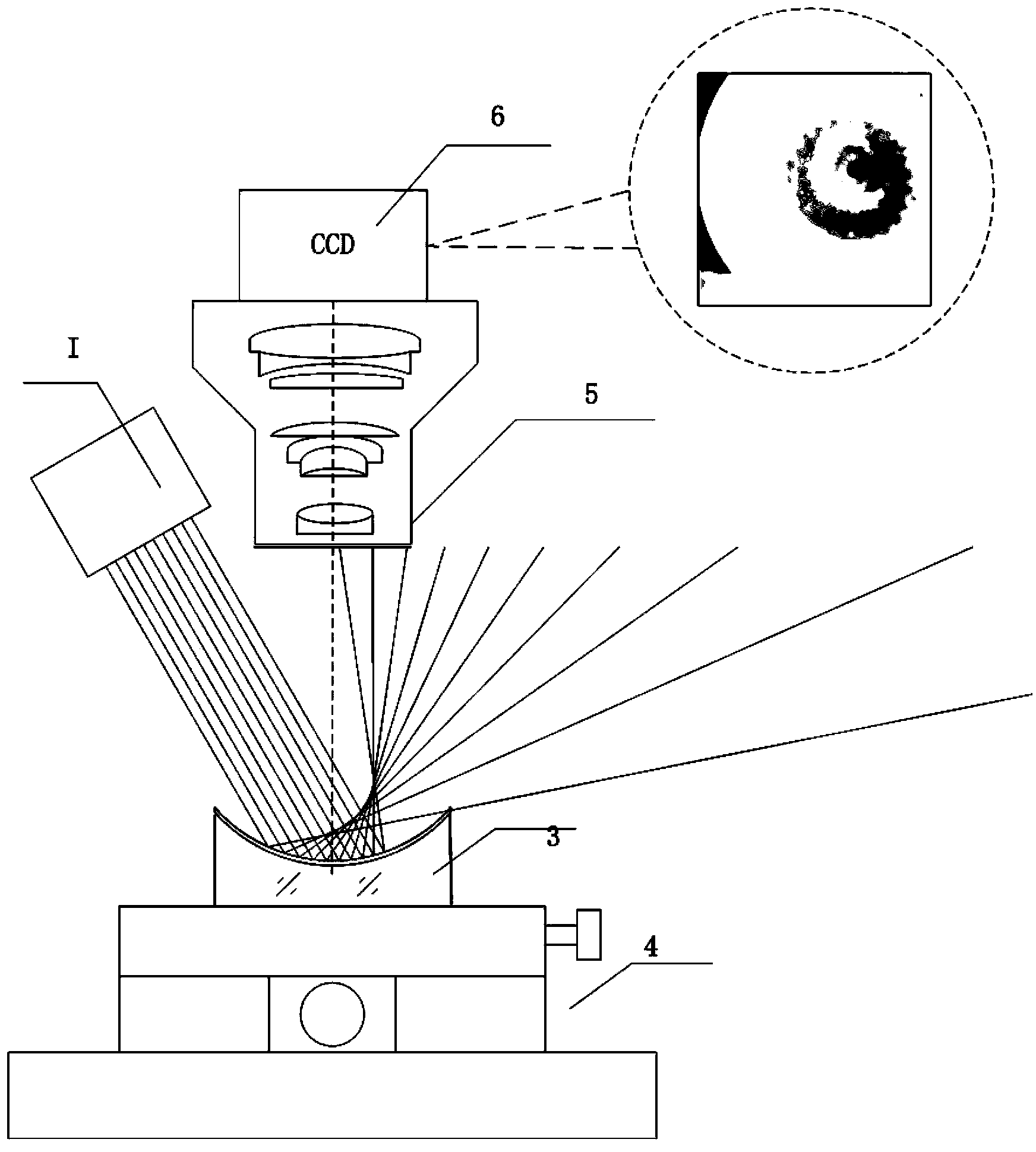
When using the same illumination source as the plane detection to detect the spherical optical element, because the spherical optical element has a certain radius of curvature, a white reflective spot will be formed on the CCD (charge coupled device), and the size of the spot varies with the curvature radius of the spherical optical element, The uneven situation changes, it is difficult to realize dark field illumination, and it is impossible to carry out follow-up detection

Method used


Image

  • Lighting system and method used for dark field detection of defect in spherical optical element surface
  • Lighting system and method used for dark field detection of defect in spherical optical element surface
  • Lighting system and method used for dark field detection of defect in spherical optical element surface

Examples


Embodiment

[0043] This embodiment is an illumination system that can be used for dark field detection of surface defects of spherical optical elements.

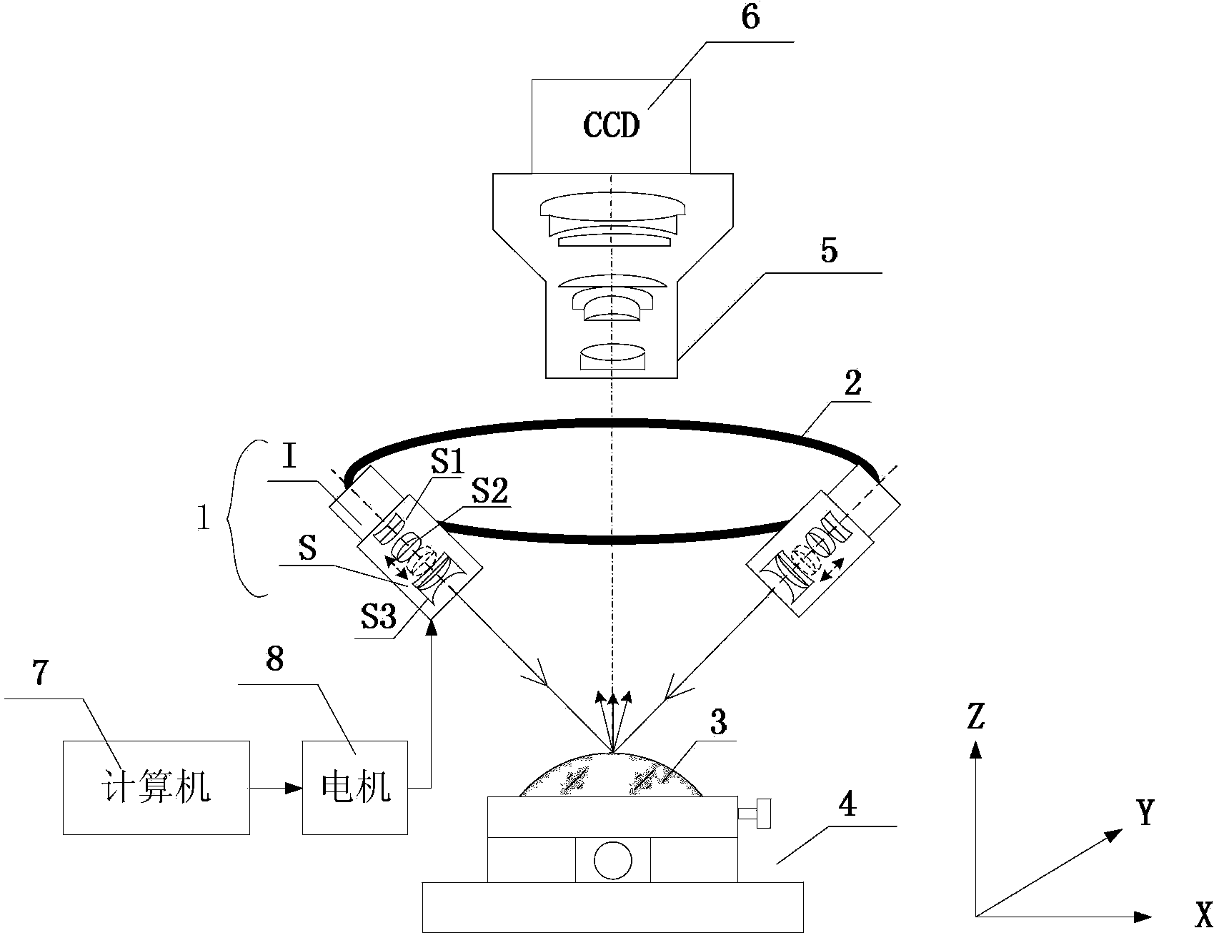
[0044] lighting system such as figure 1 As shown, it includes a spherical light source 1 , a light source bracket 2 , an optical element to be tested 3 , a clamping device 4 , a microscopic imaging system 5 , a charge-coupled device CCD 6 , a computer 7 , and a motor 8 .

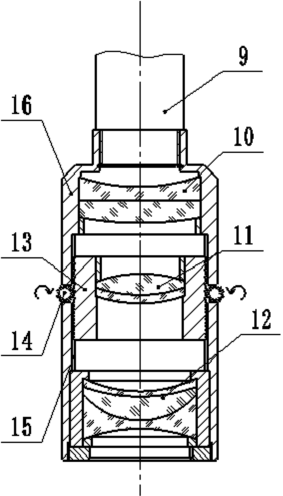
[0045] The spherical light source 1 is composed of a uniform surface light source and a lens barrel of a zoom lens group, and a plurality of light sources 1 are mounted on the light source bracket 2 at equal intervals in a ring. The mechanical structure of the zoom adjustment assembly S is as follows: figure 2 As shown, the zoom adjustment assembly S is composed of a zoom lens group lens barrel 16, a front fixed lens group 10, a zoom lens group 11, a rear fixed lens group 12, a zoom lens barrel 13, a gear 14, and a slide rail 15. Front fixed mirror group 10, zoom m...


PUM


Abstract

The invention discloses a lighting system and method used for dark field detection of a defect in a spherical optical element surface. The lighting system comprises a spherical light source, a light source support, an optical element to be detected, an optical element multidimensional holding device, a microscopic imaging system, a charge coupling element, a computer and a motor, wherein the spherical light source comprises a uniform face light source and a zoom lens group lens barrel, a plurality of spherical light sources are circlewise arranged on the light source support at equal intervals, a zoom adjusting component comprises a zoom lens group lens barrel, a front lens fixing group, a zoom lens group, a back lens fixing group, a zoom lens barrel, a gear and a sliding rail; the optical element to be detected and the holding device are arranged below the light source support, the microscopic imaging system and the charge coupling element are arranged above the light source support, and the light axis of the microscopic imaging system, the circle centre of a circular surface formed by a plurality of light sources, and the sphere centre of the optical element to be detected are coaxial. According to the dark field lighting for defect detection in the spherical optical element surface, an imaging is a bright defect image in the dark background, the contrast ratio is good, thus being easy for subsequent image processing.

Description

technical field [0001] The invention belongs to the technical field of surface defect detection of optical elements, in particular to an illumination system and method for dark field detection of surface defects of spherical optical elements. Background technique [0002] With the further development of science and technology, the requirements for optical components are getting higher and higher, especially in high-precision components such as lithography lenses and laser fusion chips, it is necessary to do precise and quantitative detection of surface defects of optical components detection. [0003] For defect detection at home and abroad, the visual method, low-pass and high-pass filter imaging methods, adaptive filter imaging methods, and angular spectrum analysis methods are basically used. However, most of these methods are only theoretical solutions, and are often limited by technical obstacles such as limited field of view and difficulty in quantification, making it...

Claims


Application Information

Patent Timeline
Patent Type & Authority Patents(China)
IPC IPC(8): G01N21/88G02B15/16
Inventor 杨甬英刘东李璐曹频
Owner ZHEJIANG UNIV
Learn More