Experimental device for testing heat conductivity coefficient of building material based on quasi steady state and unsteady state methods

An experimental device and building material technology, applied in the direction of material thermal development, etc., can solve the problems of not being able to carry the quasi-steady state method measurement process at the same time, long test time, and large relative error, so as to shorten the test preparation time and facilitate comparison and calibration. The effect of testing and reducing measurement errors

Active Publication Date: 2015-03-25
HARBIN INST OF TECH
View PDF4 Cites 0 Cited by
  • Summary
  • Abstract
  • Description
  • Claims
  • Application Information

AI Technical Summary

Problems solved by technology

[0003] The present invention solves the problem that the existing thermophysical parameter experimental device cannot carry the three measurement processes of the quasi-steady state method, the constant power method and the thermal pulse method at the same time; and there is a longer test time and a smaller maximum relative error of measurement. and other problems, and then provides an experimental device based on the quasi-unsteady method to test the thermal conductivity of building materials

Method used


Image

  • Experimental device for testing heat conductivity coefficient of building material based on quasi steady state and unsteady state methods
  • Experimental device for testing heat conductivity coefficient of building material based on quasi steady state and unsteady state methods
  • Experimental device for testing heat conductivity coefficient of building material based on quasi steady state and unsteady state methods

Examples


specific Embodiment approach 1

[0009] Embodiment 1: The experimental device based on the quasi-unsteady method for testing the thermal conductivity of building materials described in this embodiment includes an AC stabilized power supply 1, a transistor DC stabilized power supply 2, a standard resistor 3, at least one heating resistor 4, Low potential potentiometer 5, oil-immersed keyboard switch 6, ice bottle for containing ice-water mixture 7, first thermocouple 8 (temperature sensing element), second thermocouple 9; AC power supply 1 and transistor The DC stabilized power supply 2 is connected in series with two poles, the positive and negative poles of the transistor DC stabilized power supply 2 are connected to the electrical connection end of at least one heating resistor 4, and the positive pole of the transistor DC stabilized power supply 2 is connected to the current of at least one heating resistor 4 A standard resistor 3 is connected between the input terminals; the positive and negative poles of ...

specific Embodiment approach 2

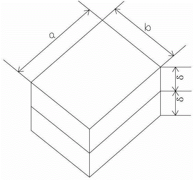
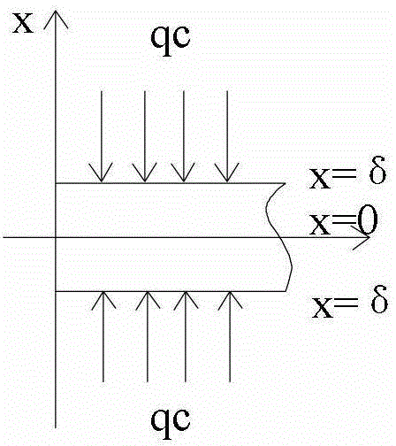
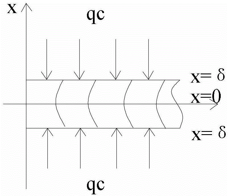
[0010] Specific implementation mode two: as Figure 4 As shown, the number of heating resistors 4 in the experimental device of this embodiment is two, and the two heating resistors 4 are connected in parallel on the transistor DC power supply 2 and the two are arranged in parallel up and down. The experimental device also includes a plurality of experimental devices. A test piece 10 and two heat insulating layers 11, a plurality of test pieces 10 are composed of the first test piece A1, the second test piece A2, the third test piece A3 and the fourth test piece A4 arranged from top to bottom with the same thickness. The second test piece A2 and the third test piece A3 are located between the two heating resistors 4, the first test piece A1 is placed on the upper heating resistor 4, and the fourth test piece A1 is placed under the lower heating resistor 4 , the first test piece A1, the second test piece A2, the third test piece A3 and the fourth test piece A4 arranged from bot...

specific Embodiment approach 3

[0011] Specific implementation mode three: as Image 6 As shown, the number of heating resistors 4 in the experimental device of this embodiment is one, and the experimental device also includes a plurality of test pieces 10, and the plurality of test pieces 10 are composed of the second test piece II, the second test piece II, and the second test piece set from top to bottom. A test piece I and a third test piece III are composed. The first test piece I is located above the heating resistor 4, and the measuring ends of the first thermocouple 8 and the second thermocouple 9 are respectively located above and below the first test piece I. On both sides, the thicknesses of the second test piece II and the third test piece III are greater than that of the first test piece I. Other components and connections are the same as those in the first embodiment.


PUM

PropertyMeasurementUnit
electrical resistanceaaaaaaaaaa
thicknessaaaaaaaaaa
diameteraaaaaaaaaa

Abstract

The invention provides an experimental device for testing a heat conductivity coefficient of a building material based on quasi steady state and unsteady state methods, relates to the field of a testing technology of thermophysical parameters of a building material, and solves the problems that an existing thermophysical parameter experimental device can not simultaneously load the measurement processes by using three methods including a quasi steady state method, a normal power method and a heat pulse method, and one-time testing time is long and a measurement maximum relative error is large. An anode and a cathode of a low-potential potentiometer are correspondingly connected with a switch control interface of an oil immersed key conversion switch; thermoelectromotive force signals output by thermocouples are respectively connected into a thermoelectromotive force signal output end of the oil immersed key conversion switch; cold ends of the thermocouples are respectively inserted into an ice bottle containing an ice-water mixture; measuring ends of the thermocouples are respectively contacted with a testing piece to be tested; a heating resistor is used for heating the testing piece to be tested. The theoretical error analysis and the actual measurement prove that the measurement maximum relative errors are as follows: the heat conductivity coefficient is less than or equal to 5.1%, the thermal diffusivity is less than or equal to 9.2% and the specific heat value is less than or equal to 7.7%; the requirement on precision by engineering is met.

Description

technical field [0001] The invention relates to an experimental device for testing the thermal conductivity of building materials based on a quasi-unsteady state method, and relates to the technical field of testing thermal physical parameters of building materials. Background technique [0002] Thermal conductivity, temperature conductivity, and specific heat are important thermophysical parameters of materials. The experimental device provided in the prior art cannot carry quasi-steady state method, constant power method, heat pulse method three kinds of measurement processes at the same time (constant power method and heat pulse method are collectively referred to as unsteady state method), which is not conducive to the accuracy of measurement results. Compare and verify. The existing experimental device still has a long test time and a relatively large maximum relative error in measurement, which cannot meet the engineering requirements for accuracy. Therefore, how to ...

Claims


Application Information

Patent Timeline
Patent Type & Authority Patents(China)
IPC IPC(8): G01N25/20
Inventor 孙澄张斌韩昀松邢凯梁静
Owner HARBIN INST OF TECH
Why Eureka
Try Eureka