Lifting mechanism suitable for tail end lifting operation of vertical equipment

A vertical equipment and tail-sliding technology, which is applied in the directions of transportation and packaging, load hanging components, etc., can solve the problems of low assembly efficiency, lost lanes, and waste, and achieves the effects of high assembly efficiency, simple structure and low risk of overturning.

Active Publication Date: 2013-09-18
SINOPEC TENTH CONSTR +1
View PDF9 Cites 4 Cited by
  • Summary
  • Abstract
  • Description
  • Claims
  • Application Information

AI Technical Summary

Problems solved by technology

[0007] 1. When the vertical equipment is hoisted, its weight is shared by the main crane and the tail crane. The tail crane needs to bear half of the weight of the vertical equipment, which means that if you hoist a heavy vertical equipment, you need Choose a small number of tail cranes with higher lifting capacity, or choose multiple tail cranes with lower lifting capacity, in either case, it will cost a lot of money
[0008] 2. The hoisting mechanism of the sliding tail crane has a long assembly cycle and low assembly efficiency. It is laborious to wind the rope during assembly, and it is prone to tangled ropes and falling off the road.

Method used


Image

  • Lifting mechanism suitable for tail end lifting operation of vertical equipment
  • Lifting mechanism suitable for tail end lifting operation of vertical equipment
  • Lifting mechanism suitable for tail end lifting operation of vertical equipment

Examples


Embodiment Construction

[0032] The technical solutions of the present invention will be described in further detail below with reference to the accompanying drawings and embodiments.

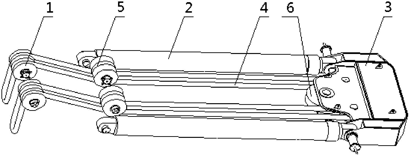
[0033] Such as image 3 As shown, it is a structural schematic diagram of an embodiment of the lifting mechanism suitable for vertical equipment hoisting and tailing operations according to the present invention. In this embodiment, the hoisting mechanism suitable for vertical equipment hoisting and tailing operations is arranged on the platform structure 8 and the crawler chassis 7 of the tailing machine (see Figure 5 installation diagram).

[0034] from image 3As can be seen in the figure, the lifting mechanism includes a horizontal push cylinder 2, a fixed pulley block 1, a movable pulley frame 3 and a cable 4. Wherein the front hinge point of the horizontal push cylinder 2 and the fixed pulley block 1 are all fixed on the crawler chassis 7, the cylinder barrel of the horizontal push cylinder 2 is installed on ...


PUM


Abstract

The invention relates to a lifting mechanism suitable for tail end lifting operation of vertical equipment. The lifting mechanism is arranged on a platform structure of a tail sliding machine and a crawler chassis. The lifting mechanism comprises a horizontal pushing oil cylinder, a fixed pulley group, a movable pulley frame and a cable, wherein a front hinged point of the horizontal pushing oil cylinder and the fixed pulley group are both fixed on the crawler chassis, and a barrel of the horizontal pushing oil cylinder is installed on the platform structure; the movable pulley frame is arranged on the upper surface of the platform structure, is fixed with a rear hinged point of the horizontal pushing oil cylinder, and is internally provided with the movable pulley group; the cable goes out of the movable pulley group and rolls the upper side of the fixed pulley group to the side, close to the crawler chassis, of the fixed pulley group so as to be connected with a lifting point on the bottom or the lower part of the vertical equipment. Compared with an existing tail sliding crane, the lifting mechanism provided by the invention is simpler in structure, is free of the working procedures, such as stringing and arm connecting, that consume long time, and has higher assembly efficiency. In addition, the operation barycenter of the complete mechanism is low, and thus the tipping risk of the complete mechanism is low.

Description

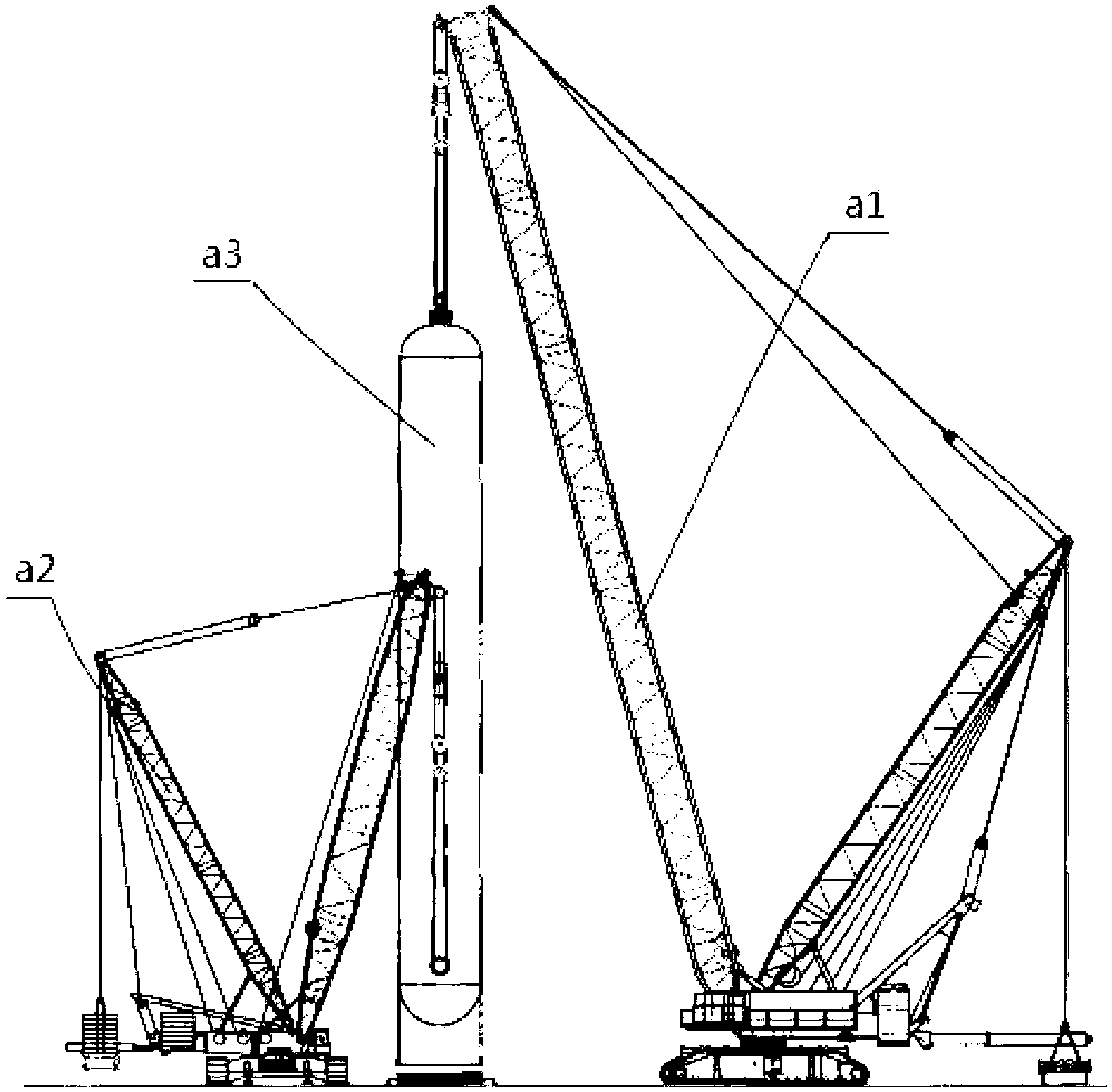
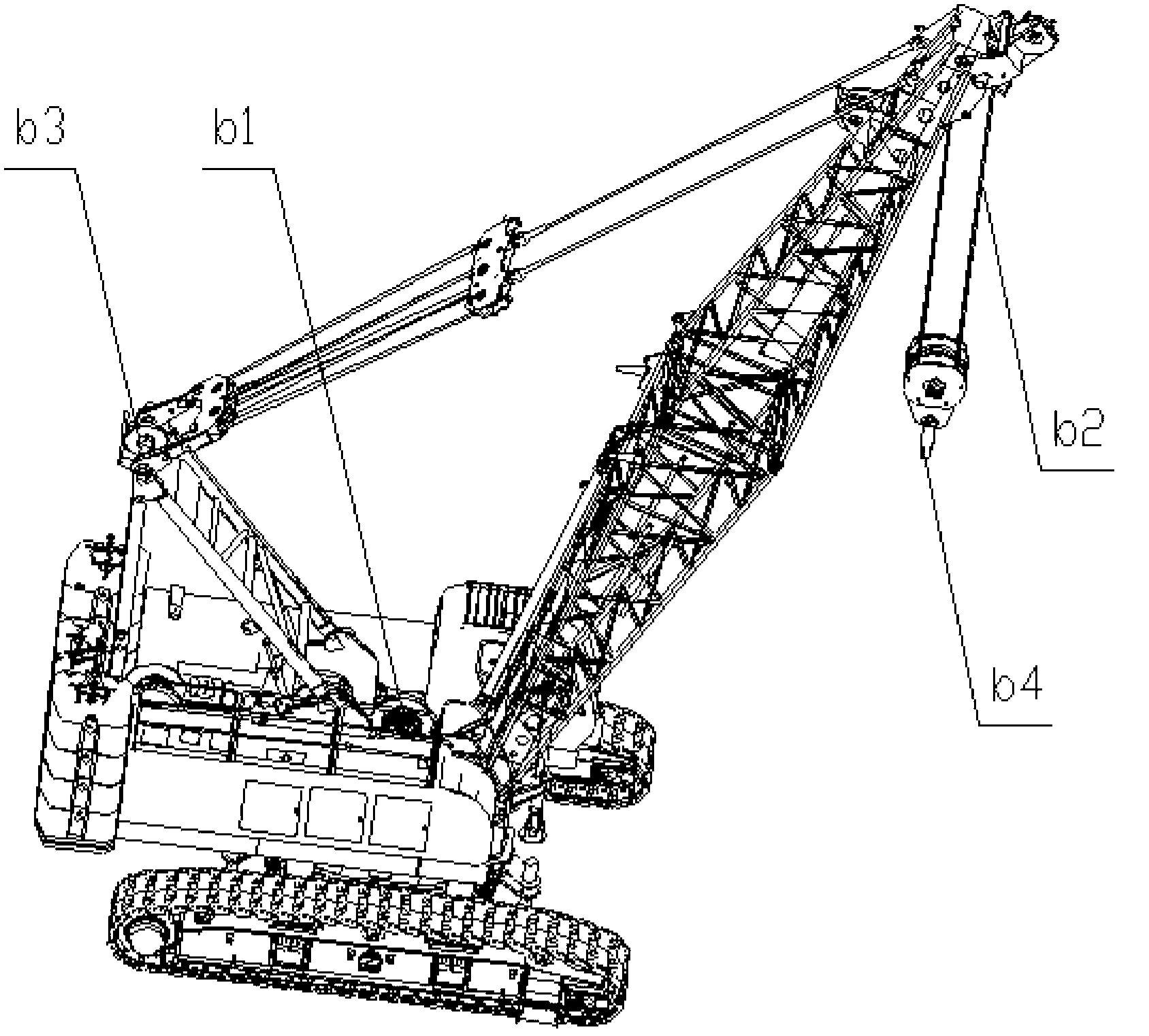
technical field [0001] The invention relates to the field of engineering machinery, in particular to a hoisting mechanism suitable for hoisting and tailing operation of vertical equipment. Background technique [0002] For the hoisting of large vertical equipment, it is usually necessary to use an auxiliary crane to assist the main crane to carry out hoisting and sliding operations. The so-called hoisting tail operation refers to the operation process of hoisting the lower end of the vertical equipment during the process of hoisting the vertical equipment from the horizontal state to the vertical state. [0003] The existing hoisting and tailing operations basically all adopt two or more cranes to carry out, one of which is the main crane, and the other is the auxiliary crane. Such as figure 1 As shown, the right crane is the main crane a1, and the left crane is the auxiliary sliding tail crane a2. It can be seen from the figure that the lifting point of the main crane a1 ...

Claims


Application Information

Patent Timeline
Patent Type & Authority Applications(China)
IPC IPC(8): B66C13/08
Inventor 孙吉产马寅孙丽章琢李龙冯强
Owner SINOPEC TENTH CONSTR
Why Eureka
Try Eureka