
Horizontal directional carbon nanotube array and preparation method thereof

A carbon nanotube array, horizontally oriented technology, applied in nanotechnology, nanotechnology, chemical instruments and methods, etc., can solve the problems that cannot be used to prepare single-wall carbon nanotube arrays, etc., and achieves fast and efficient preparation process and simple conditions. , the effect of low cost

Active Publication Date: 2013-09-18
INST OF PHYSICS - CHINESE ACAD OF SCI
View PDF3 Cites 15 Cited by
  • Summary
  • Abstract
  • Description
  • Claims
  • Application Information

AI Technical Summary

Problems solved by technology

Since super-aligned single-walled carbon nanotube arrays cannot be prepared so far, this method cannot be used to prepare horizontally oriented single-walled carbon nanotube arrays

Method used


Image

  • Horizontal directional carbon nanotube array and preparation method thereof
  • Horizontal directional carbon nanotube array and preparation method thereof
  • Horizontal directional carbon nanotube array and preparation method thereof

Examples


Embodiment 1

[0032] Step 11: growing a self-supporting single-walled carbon nanotube film with a thickness of about 200 nm by using a floating catalytic chemical vapor deposition method. The carbon nanotube film may have an orientation direction, and most of the carbon nanotubes therein generally extend along the orientation direction.

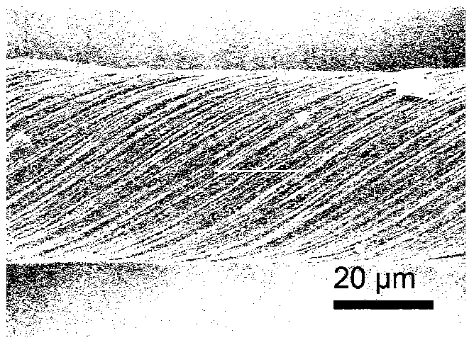
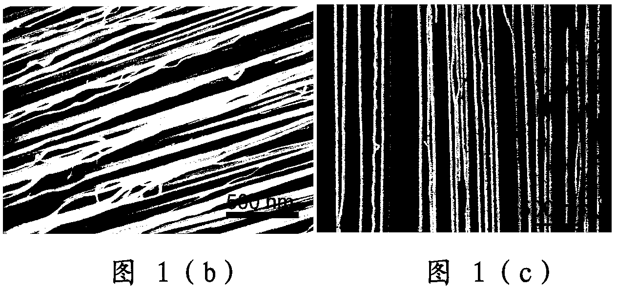
[0033] Step 12: Hold both ends of the carbon nanotube film with tweezers, and twist / twist it evenly along the orientation direction of the film to form a carbon nanotube rope with a length direction. As shown in Figure 1(a), a carbon nanotube rope has a length of about 2 cm and a diameter of about 40 μm.

[0034]The direction of the arrow in Figure 1(a) indicates the twisting direction of the carbon nanotube rope, that is, the orientation of the carbon nanotube bundle on the surface of the carbon nanotube rope. The angle between the orientation and the axial direction or length direction of the rope can indicate the degree of twisting and the magnitude of...

Embodiment 2

[0043] Step 21: growing a self-supporting single-walled carbon nanotube film with a thickness of about 100 nm by using a floating catalytic chemical vapor deposition method. Similar to Embodiment 1, the carbon nanotube film can also have an orientation direction.

[0044] Step 22: soaking the carbon nanotube film in ethanol solvent to remove the high self-adsorption of the carbon nanotube film. The ethanol liquid level can be equal to the surface of the carbon nanotube film or less than 0.5mm higher than the surface of the film.

[0045] In other embodiments, other volatile organic solvents such as water or acetone may also be used instead of ethanol.

[0046] Step 23: Clamp one end of the carbon nanotube film, and slowly "pull" the carbon nanotube film out of the ethanol. Due to the effect of gravity and surface tension, the carbon nanotube film will shrink into a strip. Nevertheless, the overall shape of the strip is still film-like. In the actual operation process, the s...


PUM

PropertyMeasurementUnit
Thicknessaaaaaaaaaa
Lengthaaaaaaaaaa
Diameteraaaaaaaaaa

Abstract

The invention discloses a horizontal directional carbon nanotube array and a preparation method thereof. The preparation method comprises the following steps of: applying a stretching force to a combination body comprising carbon nanotubes, and forming a directional carbon nanotube array in at least partial region of the surface of the combination body under the action of the stretching force; placing the combination body on a base, enabling the directional carbon nanotube array to be directly contacted with the base, applying a pressure to the combination body towards the base, and enabling at least one part of the directional carbon nanotube array to be adhered onto the base under the action of the pressure; removing the combination body from the base to obtain the horizontal directional carbon nanotube array on the base. Compared with the method for preparing the horizontal directional carbon nanotube array by adopting a direct method or an indirect method in the prior art, the method is simple, easy to popularize, quick and efficient in preparation process, and high in finished product rate.

Description

technical field [0001] The invention relates to the technical field of nanomaterial preparation, in particular to a horizontally oriented carbon nanotube array and a preparation method thereof. Background technique [0002] Horizontally oriented carbon nanotube (CNT) arrays are easy to position carbon nanotubes. Because they eliminate the influence of crossing between carbon nanotubes, they are especially suitable for the composition and integration of devices, and have potential applications in carbon nanotube electronic devices. [0003] At present, there are two main methods for preparing horizontally aligned carbon nanotubes: direct method and indirect method. Direct methods include: airflow orientation method, applied electromagnetic field method and substrate lattice orientation method, etc. The types of carbon nanotubes in the horizontally oriented carbon nanotube arrays synthesized by airflow directional method and external electromagnetic field method are not pure,...

Claims


Application Information

Patent Timeline
IPC IPC(8): C01B31/02B82Y30/00B82Y40/00C01B32/168
Inventor 牛志强周维亚解思深
Owner INST OF PHYSICS - CHINESE ACAD OF SCI
Learn More