Pressure-transmitting pin snapping and fracturing automatic grouting valve float valve

A valve and floating valve technology, applied in wellbore/well components, earthwork drilling, flushing wellbore, etc., can solve the problem of inability to guarantee a successful kill once, inaccurate shut-in riser pressure, and inaccurate killing fluid density. and other problems, to achieve the effect of speeding up the progress of oil and gas exploration, saving drilling cycle, and simple structure

Inactive Publication Date: 2013-09-18
慕武
View PDF0 Cites 3 Cited by
  • Summary
  • Abstract
  • Description
  • Claims
  • Application Information

AI Technical Summary

Problems solved by technology

This not only delays a lot of time for running in the drill (downing the oil pipe), but also increases the labor intensity of the workers. It may also cause the pressure difference sticking accident caused by the untimely movement of the drill pipe when the drilling operation is stopped to fill the drill pipe. Oil and gas exploration progress
[0003] After controlling the well kick and blowout, because the valve type float valve used on site is completely closed, the formation pressure cannot be transmitted to the standpipe pressure gauge through the liquid column to obtain the standpipe pressure, and the only way to control the small displacement is to open the throttle valve The shut-in standpipe pressure is obtained by the circulation method, but the shut-in standpipe pressure obtained in this way is inaccurate, that is, the obtained formation pressure is also inaccurate, and the inaccurate pressure calculated based on the inaccurate formation pressure The density of the well fluid cannot guarantee the success of killing the well once, and it may also cause lost circulation and other complications or accidents during the well killing process due to the inaccurate density of the well killing fluid.

Method used


Image

  • Pressure-transmitting pin snapping and fracturing automatic grouting valve float valve
  • Pressure-transmitting pin snapping and fracturing automatic grouting valve float valve

Examples


Embodiment Construction

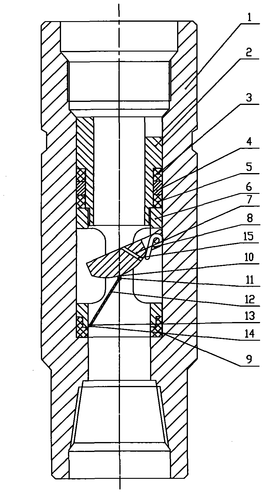
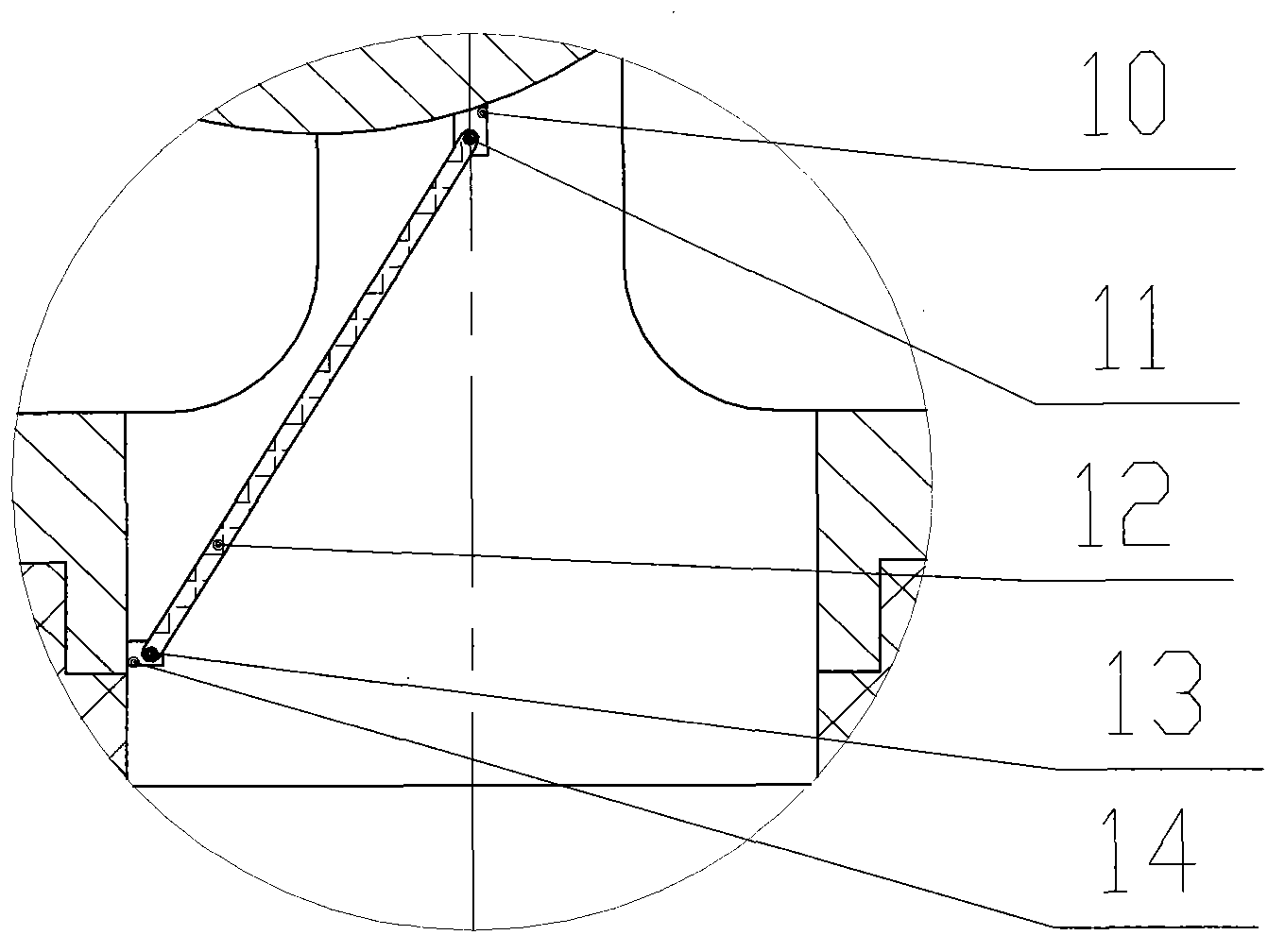
[0014] Such as figure 1 As shown, an automatic grouting valve float valve that can be pulled and broken by pressure transmission pins includes a float valve joint 1, a float valve and a valve support mechanism. The float valve is composed of an upper valve body 2, an upper sealing ring 3, a sealing gasket ring 4, The middle sealing ring 5, the valve body seat 6, the valve 7, the torsion spring 8, the lower sealing ring 9, and the pressure transmission hole 15 are formed. The hinge seat 14 is formed, the upper valve body 2 is connected with the valve body seat 6 with threads, the upper sealing ring 3, the sealing gasket ring 4, and the middle sealing ring 5 are set on the upper valve body 2, and the inner diameter of the float valve is connected with the float valve joint. The inner diameter of 1 is basically the same, and there is an inner convex shoulder surface on the inner wall of the float valve joint 1, the float valve is placed in the float valve joint 1, and the lower e...


PUM


Abstract

The invention discloses a pressure-transmitting pin snapping and fracturing automatic grouting valve float valve. The automatic grouting valve float valve is characterized in that a float valve and a valve support mechanism are mounted in a float valve joint, a valve body seat of the float valve is hinged to a valve, the elasticity of a torsion spring on both the valve and the valve body seat enables the valve to close the valve body seat when the valve is in the free state; a support bar in a valve support mechanism, through which a valve hinge mount and a valve body hinge mount, supports the elasticity of the torsion spring to enable that the valve and the valve body seat can not be closed; the valve of the float valve is in the semi-opened state to form a fluid flow passage, so that the purpose of automatic grouting can be achieved. When the pump is started after tripping, or well kick occurs in a pipe, and the force acted on the valve by fluid once the blowout slurry is reversely sprayed is larger than the tensile strength of the support bar, the support bar is snapped and fractured, and the valve, which loses the supporting force after pump stop or during well kick and blowout to be in the free state, is promptly closed under the action of the resultant force of the spring force and the like. As pressure transmitting small holes are obliquely formed in the valve, pressure of fluid inside and outside the valve after the valve is closed is transmitted.

Description

technical field [0001] The invention relates to the method of manual grouting without stopping the drilling (oil pipe running) operation in the oil drilling process, which can be automatically grouted. When the flow rate of fluid in the pump cycle or well kick or blowout pipe reaches a certain value, it will act as a check valve, which can prevent the occurrence of blowout accidents in the pipe when the drill is pulled out, and can be accurately measured after the blowout is controlled and the well is shut down. Standpipe pressure calculations yield accurate formation pressures. Background technique [0002] In the process of drilling (tubing) in oil drilling, because the valve type float valve commonly used in the field only plays the role of a check valve, and because of the limitation of the pressure bearing capacity and the compression strength of the drill pipe (tubing), the running (running) When the oil pipe) reaches a certain well depth, in order to prevent the valv...

Claims


Application Information

Patent Timeline
Patent Type & Authority Applications(China)
IPC IPC(8): E21B21/10
Inventor 慕武曾德勤贾永昌李森胡冰熊梓丞张卫贤许震李纲杨博仲
Owner 慕武
Why Eureka
Try Eureka