Drainage gas recovery device and method

A drainage gas recovery and wellhead device technology, applied in the direction of production fluid, earthwork drilling, wellbore/well components, etc., can solve the problems of high repair cost, loss of well killing fluid, great formation damage, etc., and reduce slippage loss , prolong the production cycle, and ensure the effect of formation damage

Active Publication Date: 2013-09-18
崔斌
View PDF10 Cites 25 Cited by
  • Summary
  • Abstract
  • Description
  • Claims
  • Application Information

AI Technical Summary

Problems solved by technology

[0003] The existing natural gas collection device mainly includes the first four-way connected to the downhole casing, the first tubing hanger clamped in the first four-way is connected to the first oil pipe in the downhole casing, and the first oil pipe is directly connected to the first oil pipe by using formation pressure. The downhole gas is ejected out of the wellhead, but in actual production, a large amount of formation water is mixed with natural gas. When the natural gas production is high and the flow rate in the tubing is higher than the critical point, the gas can bring the water to the surface; The production time of the gas well is prolonged, the remaining recoverable reserves of downhole gas are gradually reduced, the formation pressure, bottom hole pressure, and wellhead pressure are all continuously reduced, the flow rate in the tubing is lower than the critical point, part of the water slips into the wellbore, and the wellbore fluid accumulation reaches a certain level. Flooding is formed, so the gas cannot be removed, resulting in reduced production, or even shutdown
[0004] In order to reduce the back pressure of the wellhead, increase the output pressure, and increase the flow rate of the vertical pipe flow, the existing technology only changes the original oil pipe into a small oil pipe with a gas lift valve for production. The tubing string and the small tubing not only cause high repair costs, but also killing the well will inevitably lead to a large amount of well killing fluid leakage to the formation, which will cause great damage to the formation, and even fail to resume normal production after repair
In addition, the existing technology also uses coiled tubing drainage gas recovery (velocity string method) for gas recovery. The biggest problem of this process is that when the formation pressure continues to drop to a certain level with production, the amount of fluid accumulation at the bottom of the well continues to increase. Due to the continuous The oil pipe cannot be connected to the gas lift valve, and a new water flood is formed at the bottom of the well.

Method used


Image

  • Drainage gas recovery device and method
  • Drainage gas recovery device and method
  • Drainage gas recovery device and method

Examples


Embodiment 1

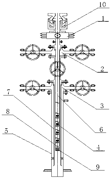
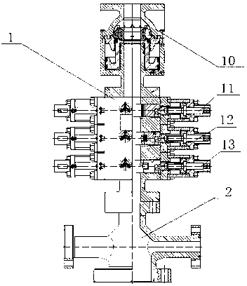
[0019] Example 1, such as figure 1 and 2 As shown, a drainage and gas production device includes a first four-way 3, a first oil pipe 6 and a casing 5, the first oil pipe 6 is embedded in the casing 5, and the bottom end of the first four-way is connected with the casing, The first oil pipe is connected with the first oil pipe hanger stuck in the first four-way, the top of the first four-way is connected with the second four-way 2, the second oil pipe hanger is stuck in the second four-way, the bottom of the second oil pipe hanger Connect the second oil pipe 7, the second oil pipe passes through the second four-way and the first four-way in sequence longitudinally, and is embedded in the first oil pipe, a closed annular cavity is formed between the first oil pipe and the second oil pipe; located in the downhole Several stages of gas-lift valves 4 are fixedly connected in the second oil pipe, the bottom end of the second oil pipe is connected with a plug 8, and a plug recovery...

Embodiment 2

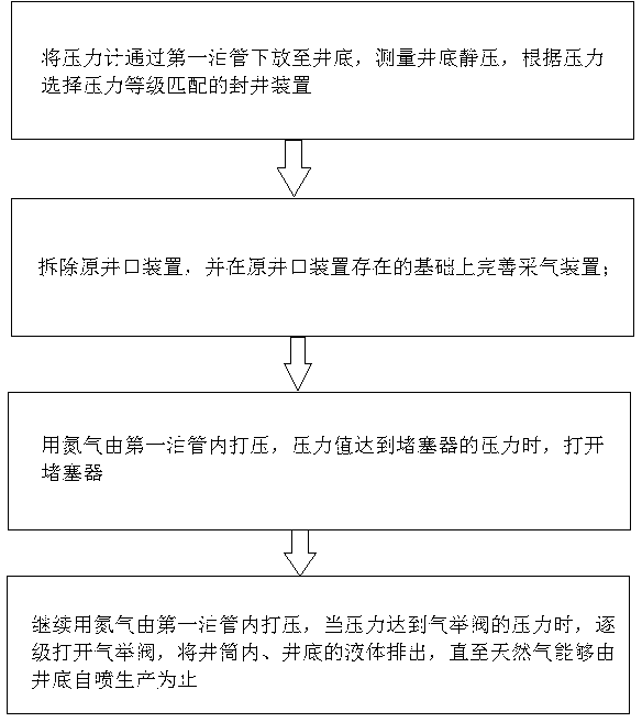
[0025] Example 2, such as image 3 Shown, a kind of drainage gas recovery method, this method comprises the following steps:

[0026] 1) Lower the pressure gauge to the bottom of the well through the first oil pipe, measure the static pressure and liquid level at the bottom of the well, select the sealing device with matching pressure level according to the pressure, and set the opening pressure value of the plug and the gas lift valve;

[0027] 2) Remove the original wellhead device, and improve the gas production device on the basis of the original wellhead device;

[0028] 3) After the gas extraction device is installed, pressurize the second oil pipe with nitrogen, and open the plug when the pressure reaches the opening pressure of the plug;

[0029] 4) Continue to use nitrogen to pressurize the second oil pipe. When the pressure reaches the opening pressure of the gas lift valve, open the gas lift valve step by step to discharge the liquid in the wellbore and the bottom ...


PUM


Abstract

The invention relates to a drainage gas recovery device and method. The method comprises the following steps of laying a pressure gauge down to the bottom of a well through a first oil pipe to measure the static pressure and the liquid level at the bottom of the well, selecting a matched well shutting device according to the pressure and setting the pressure value of a plug and a gas lift valve; dismantling an original well head, perfecting the drainage gas recovery device on the basis of existence of the original well mouth device; pressurizing a second oil pipe with nitrogen and opening the plug when the pressure of the second oil pipe reaches an opening pressure of the plug; and continuing pressurizing the second oil pipe with nitrogen and opening the gas lift valve step by step when the pressure of the second oil pipe reaches an opening pressure of the gas lift valve to drain out liquid inside the shaft and at the bottom of the well until the flowing production of natural gas is achieved. The drainage gas recovery device and method has the advantage of being capable of draining out the fluid inside the oil pipes by opening the gas lift valve through multiple flowing inducing of nitrogen lift to reduce slippage loss greatly and water accumulation, thereby prolonging the production cycle of the gas well. Besides, the drainage gas recovery device and method is easy to operate, low in cost and safe and reliable in sealing.

Description

technical field [0001] The invention relates to the field of gas recovery in oil fields (in energy exploitation), in particular to a drainage gas recovery device and method. Background technique [0002] Natural gas is a flammable gas stored deep underground. It is a clean, convenient and efficient fuel, and an important chemical raw material with high economic value. [0003] The existing natural gas collection device mainly includes the first four-way connected to the downhole casing, the first tubing hanger clamped in the first four-way is connected to the first oil pipe in the downhole casing, and the first oil pipe is directly connected to the first oil pipe by using formation pressure. The downhole gas is ejected out of the wellhead, but in actual production, a large amount of formation water is mixed with natural gas. When the natural gas production is high and the flow rate in the tubing is higher than the critical point, the gas can bring the water to the surface; ...

Claims


Application Information

Patent Timeline
Patent Type & Authority Applications(China)
IPC IPC(8): E21B43/00
Inventor 崔斌
Owner 崔斌
Why Eureka
Try Eureka