Compact bus groove case

A busway and intensive technology, applied in the direction of open busway installation, etc., can solve the problems that the waterproof effect cannot be guaranteed, affect the safe operation of equipment, and the sealant is easy to age and fall off, so as to improve the waterproof effect and facilitate manufacturing and installation , the effect of simple structure

Inactive Publication Date: 2009-07-08
WETOWN ELECTRIC GRP CO LTD
View PDF0 Cites 7 Cited by
  • Summary
  • Abstract
  • Description
  • Claims
  • Application Information

AI Technical Summary

Problems solved by technology

This structure not only has many connection points on the shell, but also requires a lot of assembly work, and the connection part of the shell is easy to seep water during use, which affects the safe operation of the equipment. Therefore, it is usually necessary to seal the joint between the side plate and the top plate. glue, which further increases the installation workload, and the sealant is easy to age and fall off during the operation of the equipment, so the waterproof effect cannot be guaranteed

Method used


Image

  • Compact bus groove case
  • Compact bus groove case
  • Compact bus groove case

Examples


Embodiment Construction

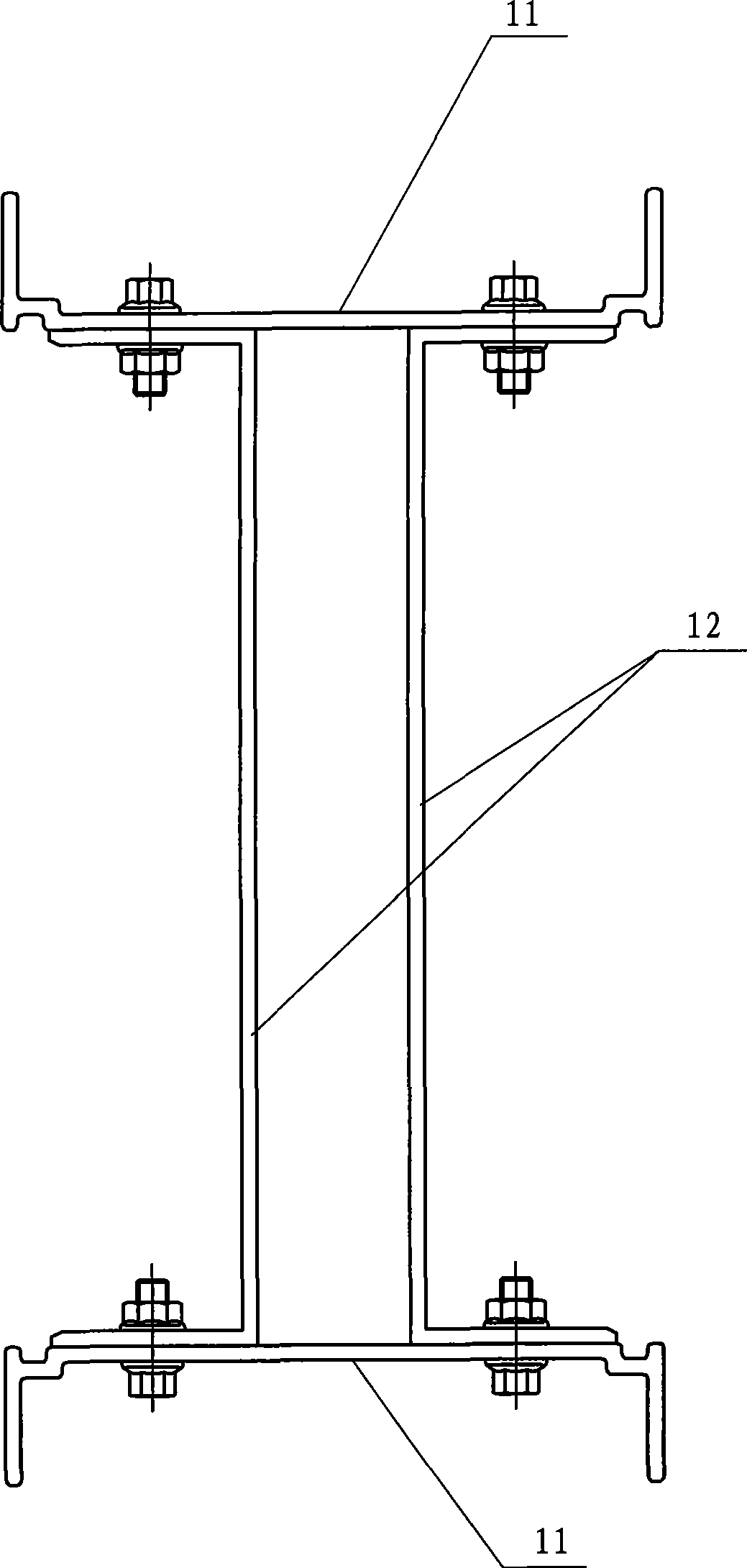
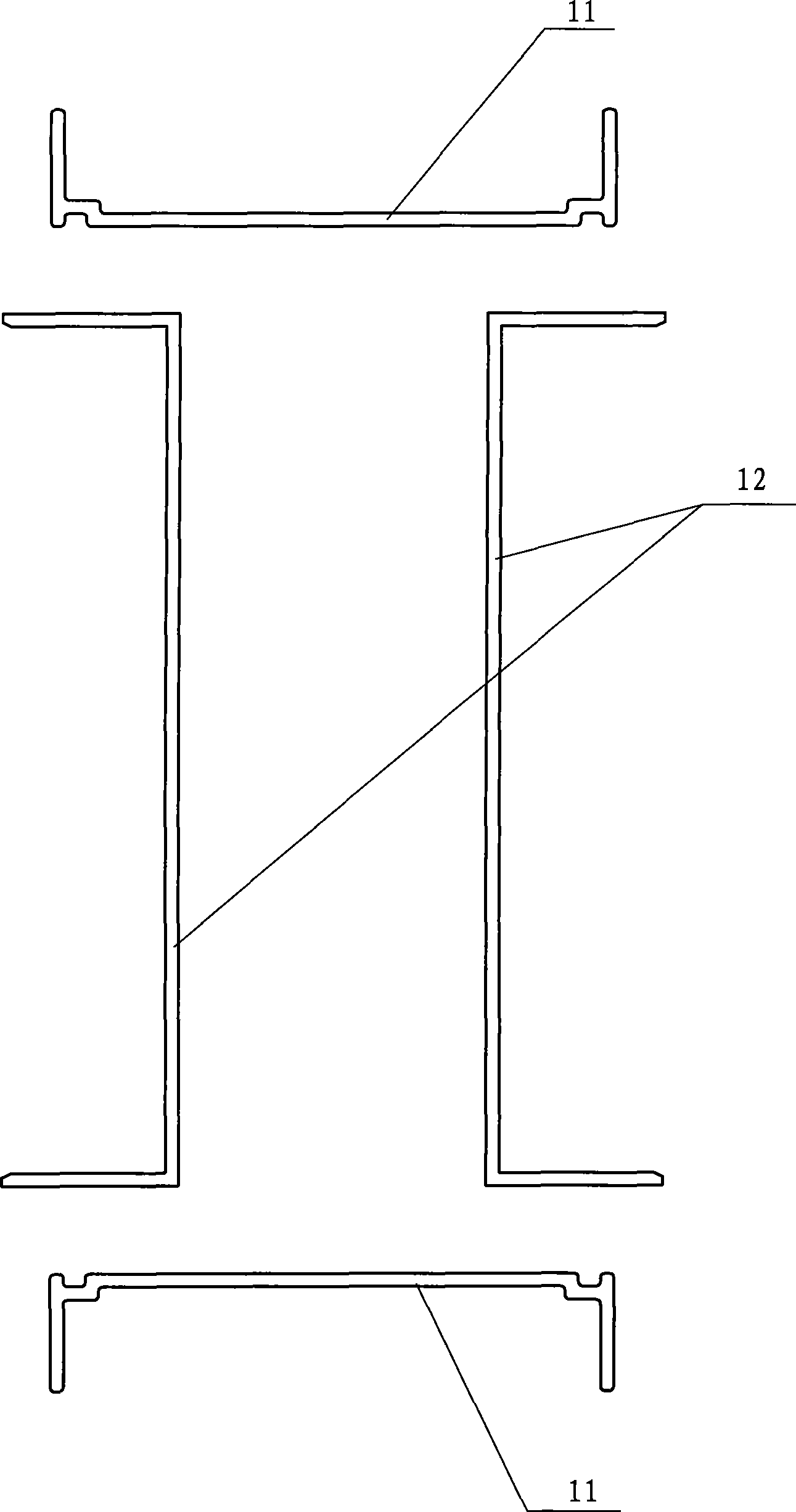
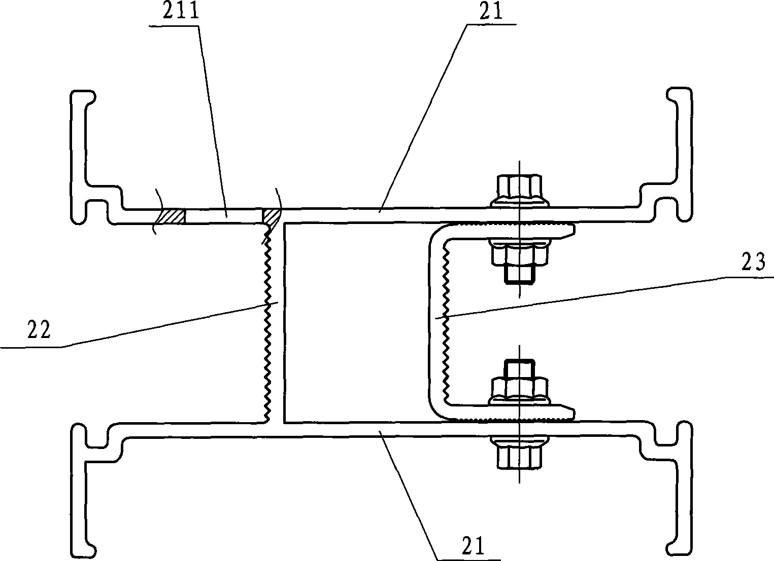
[0015] Such as image 3 , Figure 4 As shown, the dense busway housing includes two upper and lower cover plates 21 and a fixed side plate 22 connected between the two cover plates and biased to one side. The two cover plates 21 and the fixed side plate 22 are separated by The integral structure is made of aluminum alloy profiles. A movable side plate 23 with a C-shaped cross section is arranged between the two cover plates and is biased to the other side. The folding edges 231 on the lower and lower ends of the movable side plate pass through the cover plate. Connect and fix with bolts or rivets. A drainage hole 211 is also opened on the upper cover plate 21, and the lateral position of the drainage hole is located outside the fixed side plate 22.

[0016] A number of longitudinal occlusal ribs 24 are provided on the surfaces where the folding edges 231 on the movable side plate and the lower ends meet the cover plate, such as Figure 5 As shown, the top of the occlusal ribs has ...


PUM


Abstract

The invention belongs to transmission facility, which relates to a compact bus duct housing, which comprises an upper cover plate, a lower cover plate and a fixed side plate connected between the two cover plates and biased towards one side. The two cover plates and the fixed side plate are made of aluminum alloy sectional bars in monolithic construction. A flexible side plate with C-shaped cross section is arranged between the two cover plates, and is biased towards the other side. The folded edges at the upper end and the lower end of the flexible side plate are fixedly connected with the cover plates through bolts or rivets. The compact bus duct housing has the advantages of simple structure, convenient installation and effective watertightness.

Description

Technical field [0001] The invention belongs to power transmission equipment and relates to a dense busbar casing. Background technique [0002] In the existing transmission bus system, the shell structure of the dense bus duct is usually as attached figure 1 And figure 2 As shown, it is composed of two upper and lower cover plates 11 and two C-shaped side plates 12 on both sides. The folded edges of the side plates and the lower ends are respectively connected and fixed to the two cover plates by bolts or rivets. This structure not only has many connection points on the shell, but also requires a lot of assembly work, and the connecting part of the shell is easy to seep into the water during use, which affects the safe operation of the equipment. Therefore, it is usually necessary to seal the connection between the side plate and the top plate. Glue, which further increases the installation workload, and during the operation of the equipment, the sealant is also easy to age an...

Claims


Application Information

Patent Timeline
Patent Type & Authority Applications(China)
IPC IPC(8): H02G5/02
Inventor 蒋文功常小勇
Owner WETOWN ELECTRIC GRP CO LTD
Why Eureka
Try Eureka