
Biomass horizontal type cyclone burning boiler

A biomass and cyclone technology, applied in the direction of combustion methods, blast equipment, combustion equipment, etc., can solve problems such as furnace blockage, boiler black smoke, fuel cannot be fully burned, etc., and achieve the effect that is conducive to high temperature requirements

Active Publication Date: 2013-09-18
胡光
View PDF5 Cites 7 Cited by
  • Summary
  • Abstract
  • Description
  • Claims
  • Application Information

AI Technical Summary

Problems solved by technology

[0002] Traditional biomass small boilers use a vertical furnace and fixed grate. If the biomass fuel is coked, the fixed grate will be gradually accumulated by coking bodies after long-term combustion, causing the furnace to be blocked. Due to the lack of oxygen due to the blockage of the grate, the boiler burns and emits black smoke
Therefore, the problems existing in the existing small biomass boilers are: the fuel cannot be fully burned, and the heat energy of the fuel is not fully utilized; the coking cannot be removed, and manual treatment is required

Method used


Image

  • Biomass horizontal type cyclone burning boiler
  • Biomass horizontal type cyclone burning boiler
  • Biomass horizontal type cyclone burning boiler

Examples


Embodiment Construction

[0021] The specific implementation manner of the present technology will be further described below in conjunction with the accompanying drawings.

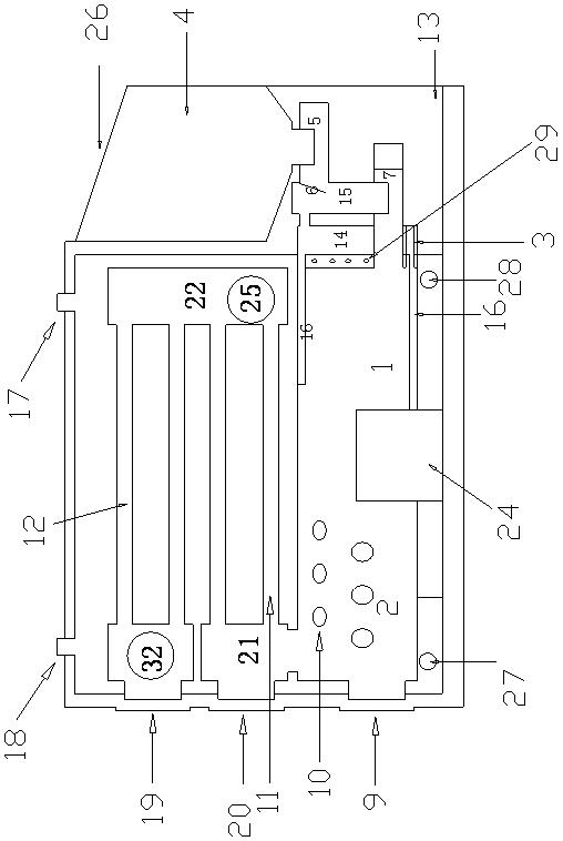
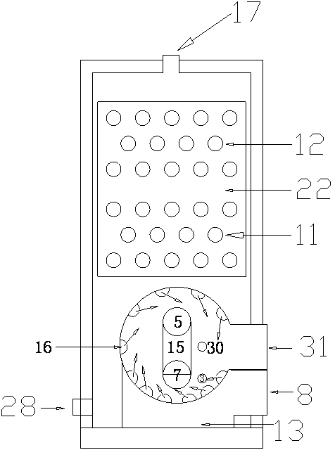
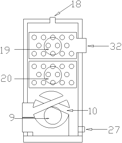
[0022] Such as figure 1 In the shown biomass horizontal cyclone boiler, the combustion chamber 1 includes the combustion chamber 1 and the combustion chamber 2 connected. The inner wall of the combustion chamber 1 is provided with a horizontal cyclone air duct. The horizontal cyclone air duct 16 is semi-cylindrical, the right end (front end) is closed, and the left end (rear end) passes through the jacket layer 29 and communicates with the blast air distribution cavity 14 . The rear end of the combustion chamber 1 is provided with a jacket layer 29 which is isolated from the blast air distribution chamber 14, and the side wall on the right side of the jacket layer 29 forms the combustion chamber back plate. The jacket layer communicates with the water chamber 33 through holes. The first fuel feed channel passes through the air ...


PUM


Abstract

The technology provides a biomass horizontal type cyclone burning boiler, which can allow fuels to burn sufficiently, prevent the fuels from coking and stack, and is convenient and comfortable to use and maintain. The boiler comprises horizontal type cyclone air pipes and a horizontal type combustor, wherein a plurality of the semi-cylindrical cyclone air pipes are evenly arranged on the inner wall at the back end of the combustor; front ends, positioned inside the combustor, of the cyclone air pipes are sealed, and the back ends of the cyclone air pipes are communicated with an airing and air distributing chamber; the front end of the combustor is communicated with a heat transfer smoke pipe, and the back end of the combustor is separated by a combustor back plate and the airing and air distributing chamber; a slag box is arranged at the lower part of connecting parts of the front ends of the cyclone air pipes and the combustor; a heat transferring medium chamber is arranged on the periphery of the combustor and the heat exchange smoke pipe; a first feeding packing auger is arranged in a first fuel feeding channel; a blower nozzle is arranged on the first fuel feeding channel; air outlets are formed in pipe walls of the cyclone air pipes, axial directions of the air outlets and the radial direction of the combustor form acute angles to allow airs entering into the combustor from the air outlets to form an eddy rotating in a same direction; and the airing and air distributing chamber is communicated with an outlet of the combustor.

Description

technical field [0001] The technology relates to a burner, specifically, a biomass horizontal cyclone fired boiler. Background technique [0002] Traditional biomass small boilers use a vertical furnace and fixed grate. If the biomass fuel is coked, the fixed grate will be gradually accumulated by coking bodies after long-term combustion, causing the furnace to be blocked. Due to the blockage of the grate and the lack of oxygen, the boiler burns and emits black smoke. Therefore, the problems existing in the existing small biomass boilers are: the fuel cannot be fully burned, and the heat energy of the fuel is not fully utilized; the coking cannot be removed, and manual treatment is required. Contents of the invention [0003] The purpose of this technology is to provide a biomass horizontal cyclone boiler that can fully burn the fuel, prevent fuel coking and accumulation, and is easy to use and maintain. [0004] In order to solve the above problems, the technical soluti...

Claims


Application Information

Patent Timeline
Patent Type & Authority Applications(China)
IPC IPC(8): F23B40/06F23B90/06F23K3/00F23L5/02F23J15/06F23J9/00
CPCY02E20/30
Inventor 胡光
Owner 胡光
Learn More