Single-phase combined co-phased power supply and transformation structure

A combined technology for power supply and transformation, applied in the field of single-phase combined power supply and transformation structure, can solve the problems of YNd11 wiring traction transformer capacity waste, traction transformer capacity idle, affecting economy, etc., to improve power supply resources and equipment Utilization rate, reduction of one-time investment, and effect of increasing energy saving effect

Active Publication Date: 2013-09-18
CHENGDU SHANGHUA ELECTRIC CO LTD
View PDF3 Cites 37 Cited by
  • Summary
  • Abstract
  • Description
  • Claims
  • Application Information

AI Technical Summary

Problems solved by technology

However, in the case where the three-phase voltage unbalance (negative sequence) does not meet the standard, it is necessary to install the same-phase (symmetrical) compensation device, which needs to be compensated at the three ports on the traction side, and the structure is more complicated. At the same time, compared with the minimum It is necessary to add 1/3 of the same-phase compensation capacity. In addition, when the three-phase voltage unbalance (negative sequence) meets the requirements and does not need the same-phase (symmetrical) compensation, using one of the phases for the same-phase power supply will cause YNd11 wiring traction transformers Large waste of capacity (up to 2/3), very uneconomical
Therefore, it is difficult to promote YNd11 wiring traction transformers to implement same-phase power supply on the whole line of new railways
[0007] In addition to the sing

Method used


Image

  • Single-phase combined co-phased power supply and transformation structure
  • Single-phase combined co-phased power supply and transformation structure
  • Single-phase combined co-phased power supply and transformation structure

Examples


Embodiment

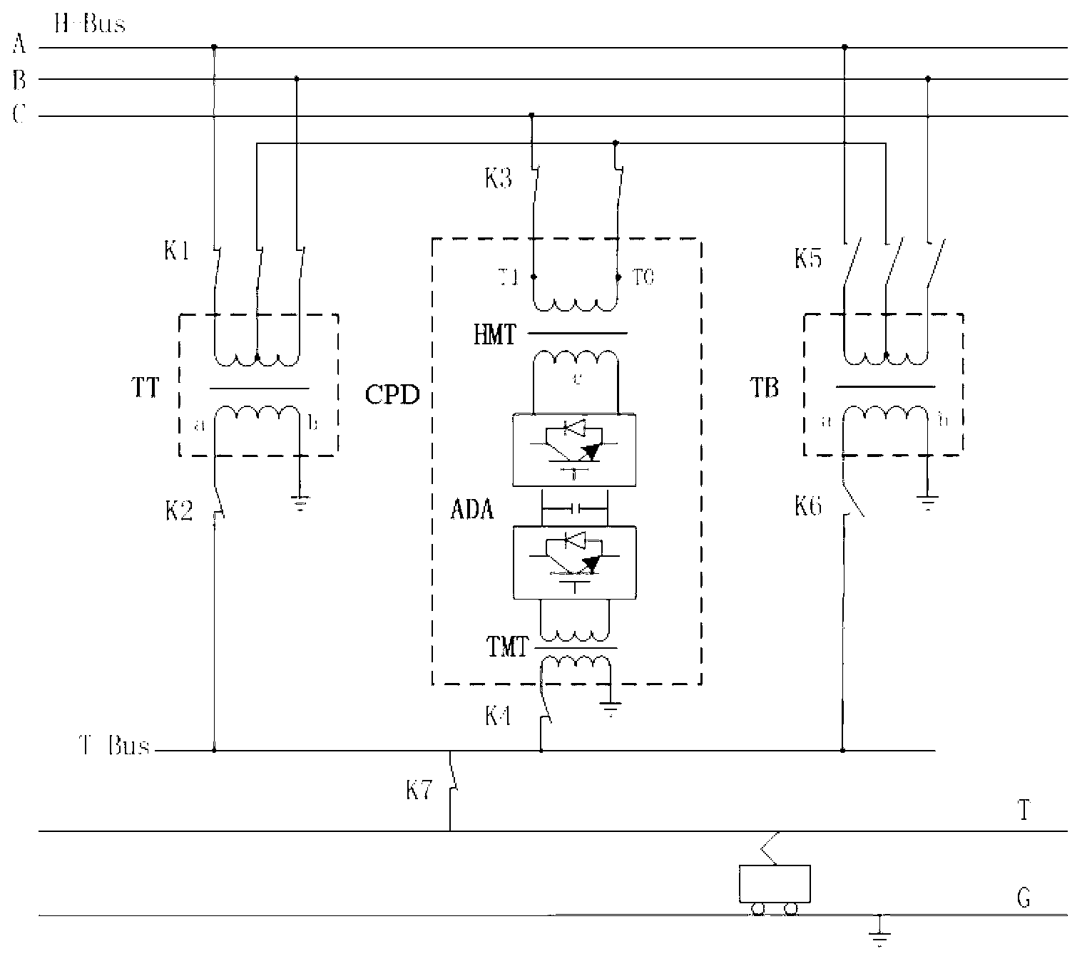
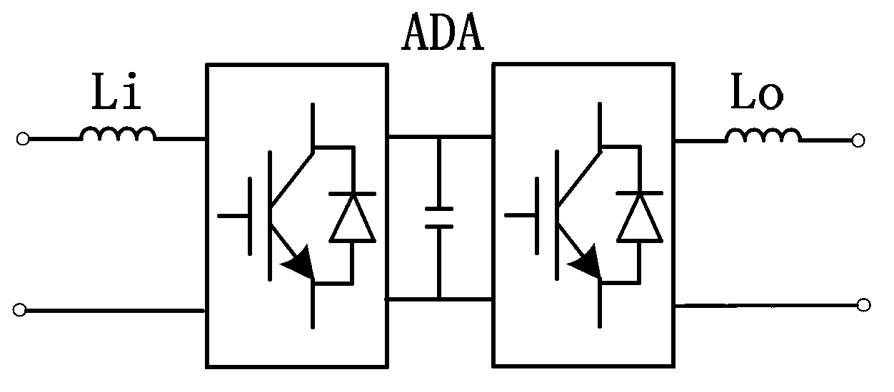
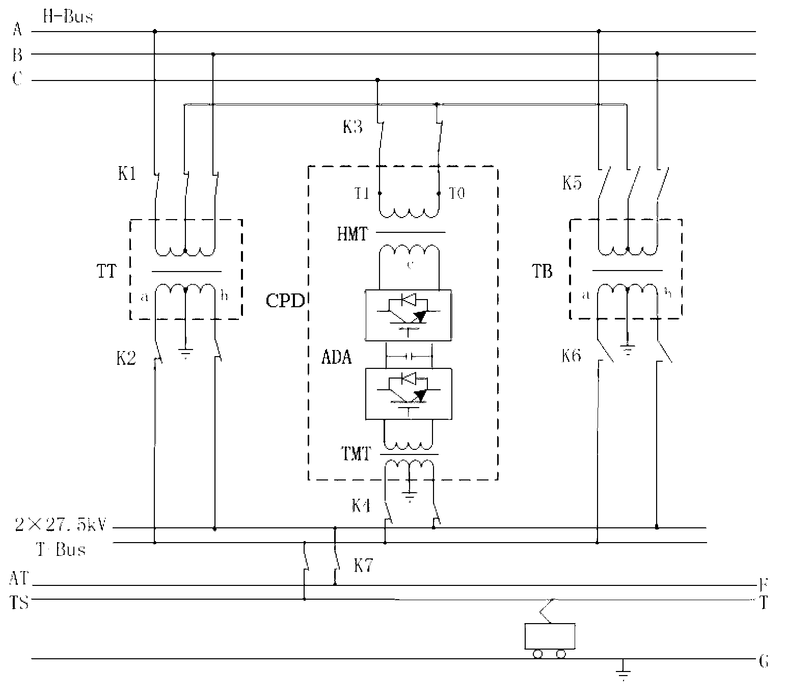
[0030] Such as figure 1 As shown, a schematic diagram of a common-phase power supply and transformation structure, including a traction transformer (TT), a backup traction transformer (TB) and a common-phase compensation device (CPD); the common-phase compensation device (CPD) consists of a high-voltage matching transformer (HMT), an AC-DC-AC ADA and traction matching transformer (TMT); traction transformer (TT), standby traction transformer (TB) and common phase compensation device (CPD) are all single-phase structures; one end of the primary winding of high voltage matching transformer (HMT) T0 is respectively connected to the middle points of the primary windings of the traction transformer (TT) and the standby traction transformer (TB); the primary winding of the traction transformer (TT) and the primary winding of the standby traction transformer (TB) are connected to the high voltage bus H-Bus of the power system The same line voltage, the figure shows the AB line voltag...


PUM


Abstract

The invention discloses a single-phase combined in-phase power supply and transformation structure mainly comprising a traction transformer and a CPD. In the CPD, a high-voltage matching transformer primary side and a traction transformer primary side form an SCOTT connected group, a secondary side winding of the CPD is connected to the incoming end of an AC-DC-AC converter, and the outgoing end of the AC-DC-AC converter is connected with the primary side of a traction matching transformer. A secondary side winding of the traction transformer and the secondary side winding of the traction matching transformer are equal in voltage amplitude and phase and both connected with a traction busbar; traction load calculated capacity is equal to the sum of traction transformer calculated capacity and CPD calculated capacity, the traction transformer is responsible for main power supply, and the CPD calculated capacity is determined by the capacity of traction load which caused exceeding three-phase voltage unbalance. The single-phase combined in-phase power supply and transformation structure has the advantages that optima configuration of traction power supply resources is realized and energy conservation is better.

Description

technical field [0001] The invention relates to the field of AC electrified railway power supply, in particular to a single-phase combined in-phase power supply and transformation structure. Background technique [0002] Electrified railways generally adopt the single-phase power frequency AC system powered by the public power system. In order to make the single-phase traction load be distributed as balanced as possible in the three-phase power system, the electrified railway often adopts the scheme of rotating phase sequence and separate phase and partition power supply. The adjacent power supply areas at the phase-splitting partitions are divided by phase-splitting insulators to form electrical split phases, also known as phase splits. In order to prevent electric locomotives from burning out catenary suspension components due to arcing through electric split-phase emission, and even causing phase-to-phase short-circuit and other accidents, as the train speed continues to ...

Claims


Application Information

Patent Timeline
IPC IPC(8): H02J3/00H02J3/26
CPCY02E40/50
Inventor 李群湛吴命利郭锴解绍锋高仕斌舒泽亮郭育华李亚楠蒋先国侯日根宫衍圣杨振龙黄足平魏宏伟曹广河张剑吴河邓云川汪吉健刘炜楚振宇夏焰坤李子晗赵元哲
Owner CHENGDU SHANGHUA ELECTRIC CO LTD
Why Eureka
Try Eureka