Demoulding device for lift-sub type packaging of batteries

A demoulding device and elevator-type technology, which is applied in packaging and other directions, can solve the problems of slow manual operation, low efficiency, and high labor intensity, and achieve the effects of saving labor costs, high work efficiency, and high operation accuracy

Active Publication Date: 2013-09-25
ZHONGYIN NINGBO BATTERY CO LTD
View PDF9 Cites 2 Cited by
  • Summary
  • Abstract
  • Description
  • Claims
  • Application Information

AI Technical Summary

Problems solved by technology

[0003] Since the existing technology is completely manual demoulding, but manual operation is slow, labor-intensive, and inefficient, which increases the number of people employed by the enterprise. However, at the moment when the labor force is in short supply and labor costs are rising, the traditional demoulding method obviously cannot To meet the needs of the survival and development of the enterprise; more importantly, after hot pressing, the curling of the plastic foam and the upper edge of the cavity of the mold cavity are closely attached, and it is difficult to pick the curling of the plastic foam and the upper edge of the pit by manual operation Digging and separation, especially because the hot pressing has just been completed, the glue between the elevator and the plastic bubble has not completely cooled, and the bonding strength between each other is not strong. During the manual digging and separation process, the operator must be careful and slightly careless If the force is too large or the angle is unreasonable, the glue between the plastic bubble and the elevator will be destroyed and the plastic bubble will be separated from the elevator; moreover, there is also a force in the process of manually placing the plastic bubble to the second conveying device. Improper, plastic bubbles and elevators detached

Method used


Image

  • Demoulding device for lift-sub type packaging of batteries
  • Demoulding device for lift-sub type packaging of batteries
  • Demoulding device for lift-sub type packaging of batteries

Examples


Embodiment Construction

[0019] The present invention will be further described below in conjunction with the accompanying drawings and specific embodiments.

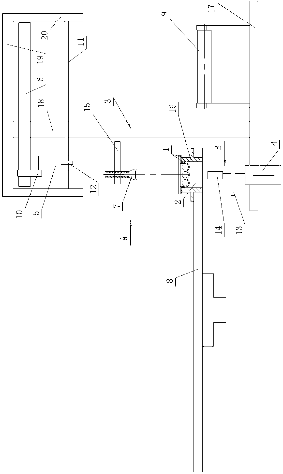
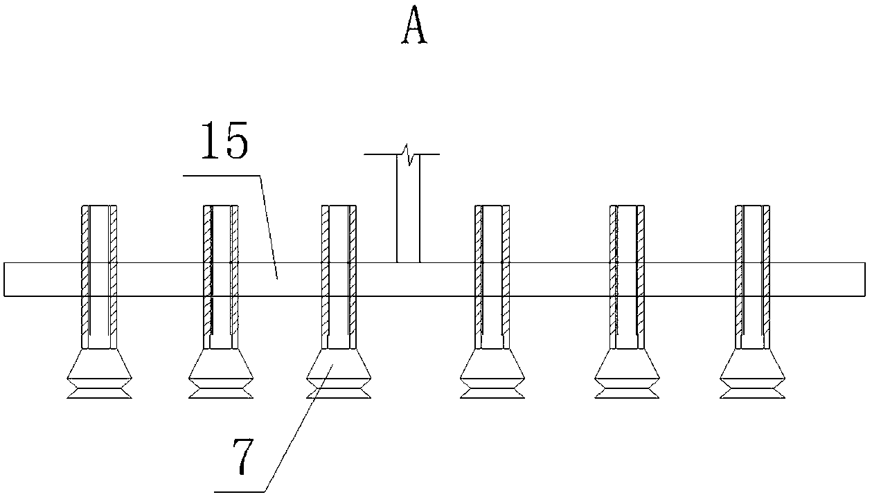
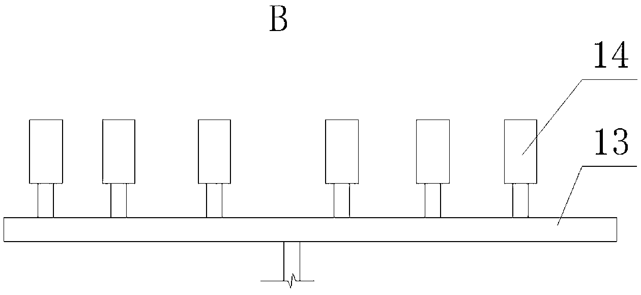
[0020] Such as figure 1 , figure 2 , image 3 As shown, the demoulding device of the present invention is used for battery elevator packaging, which includes a bracket 3, a mold cavity 2 for accommodating plastic bubbles 1 arranged on the first conveying device, and a mold cavity 2 for transporting demoulded plastic bubbles 1 the second conveyor. In this embodiment, the first conveying device is a turntable 8 , and the second conveying device is an automatic conveyor belt 9 . The mold cavity 2 is a through hole passing through the first conveying device. Specifically, the turntable 8 is penetrated with a plurality of installation holes, and the installation holes are detachably connected with the mold 16. The mold cavity 2 is located in the mold 16 and the mold cavity 2 runs through the mold. 16.

[0021] A demoulding cylinder 4 for loose...


PUM


Abstract

The invention discloses a demoulding device for lift-sub type packaging of batteries. The demoulding device comprises a mould cavity (2) arranged on a first conveyor, a second conveyor and a support (3). The mould cavity (2) is a through hole. A demoulding air cylinder (4), a lifting air cylinder (5) and a conveying air cylinder (6) are mounted on the support (3). The demoulding air cylinder (4) is used for ejecting plastic bubbles (1) to be loosened from the mould cavity (2). The lifting air cylinder (5) is used for taking the plastic bubbles (1) out of the mould cavity (2). The conveying air cylinder (6) is used for conveying the plastic bubbles (1) to the second conveyor. A piston rod of the demoulding air cylinder (4) is positioned below a demoulding station of the first conveyor. An air cylinder wall of the lifting air cylinder (5) is fixed on a movable piece of the conveying air cylinder (6). A piston rod of the lifting air cylinder (5) is provided with a suction nozzle (7) which is positioned above the demoulding station of the first conveyor. With the demoulding device, speed is increased, working efficiency is improved, labor intensity is reduced, labor cost is saved, and the plastic bubbles (1) are prevented from being separated from a lift sub.

Description

technical field [0001] The invention relates to battery packaging equipment, in particular to a demoulding device for battery elevator packaging. Background technique [0002] Elevator packaging of batteries refers to the packaging method of wrapping batteries with elevators and plastic bubbles fixed on the elevators. Elevator packaging needs to put the battery into the plastic bubble, and spray glue on the edge of the opening of the plastic bubble or on the elevator, and then press and bond the curling of the plastic bubble and the elevator with a hot pressing plate , namely hot pressing. The specific process of hot pressing is as follows: the main part of the plastic bubble battery is placed in the concave cavity of the first conveying device such as a turntable, the opening of the plastic bubble is placed upwards, and a circle of the curling edge of the plastic bubble opening is placed in the concave cavity of the mold cavity. On the upper edge of the pit, the plastic b...

Claims


Application Information

Patent Timeline
Patent Type & Authority Applications(China)
IPC IPC(8): B65B61/28
Inventor 王海兵胡新凯王幸尧
Owner ZHONGYIN NINGBO BATTERY CO LTD
Why Eureka
Try Eureka