Series-parallel combined high-efficient hydrogen oxygen electrolytic bath

An electrolytic cell, hydrogen and oxygen technology, applied in the field of electrolytic cells, can solve the problems of low utilization rate of electrolytic materials, large bypass parasitic current, affecting the life of electrolytic cells, etc., and achieve the effect of consistent life, consistent current density, and improved efficiency

Inactive Publication Date: 2013-09-25
武汉微氢科技有限公司
View PDF5 Cites 4 Cited by
  • Summary
  • Abstract
  • Description
  • Claims
  • Application Information

AI Technical Summary

Problems solved by technology

[0003] The structure of the currently used electrolytic cell is like the "combined high-efficiency hydrogen-oxygen electrolytic cell" with the patent application number 201010238025.7. The current utilization rate becomes smaller, and the bolt welds are easily broken by electric corrosion. The electrolytic cell is sealed by the rubber ring between the channel steel and the nylon plate. If the time is long, it will easily cause lye leakage, affecting the life of the overall electrolytic cell, and the utilization rate of electrolytic materials is low.

Method used


Image

  • Series-parallel combined high-efficient hydrogen oxygen electrolytic bath
  • Series-parallel combined high-efficient hydrogen oxygen electrolytic bath
  • Series-parallel combined high-efficient hydrogen oxygen electrolytic bath

Examples


Embodiment Construction

[0015] The present invention is described in detail in conjunction with the accompanying drawings.

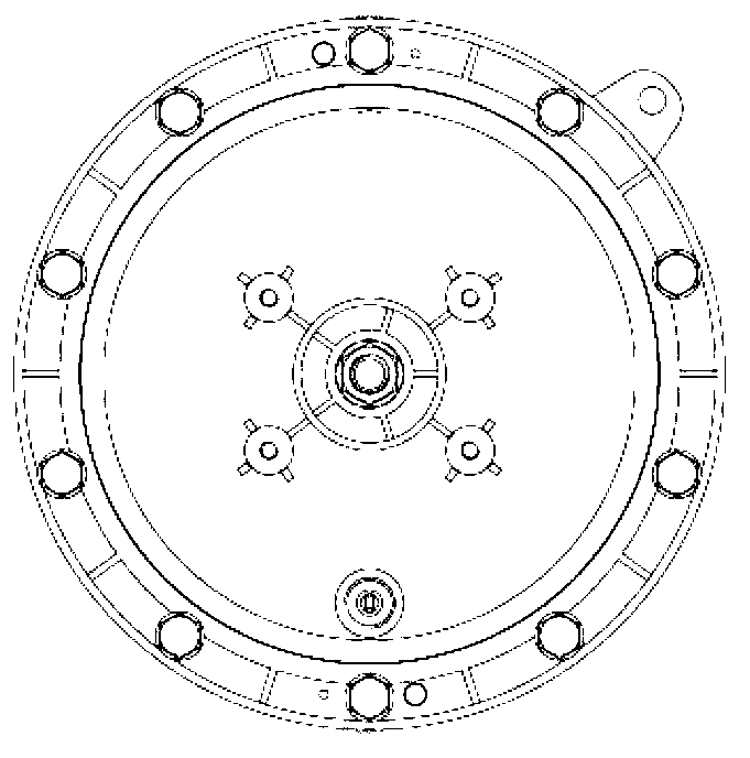
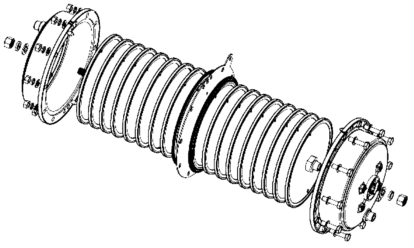
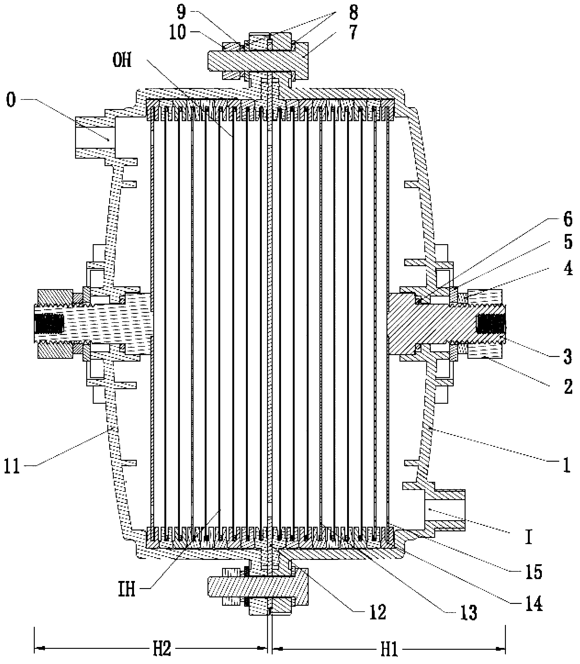
[0016] Such as figure 1 , figure 2 , image 3 As shown, the present invention includes: an electrolytic cell housing (1, 11), a positive electrode plate 12, 16 intermediate electrode plates 13, and two negative electrode plates 15. The electrolytic cell housing is respectively provided with a liquid inlet I and a gas-liquid outlet O , the electrolyzer housing is formed by locking the left housing 11 and the right housing 1 with bolts 7, flat washers 8, spring washers 9 and nuts 10 through screw holes, and the left housing 11 forms a semi-closed left cylinder H2 , the right housing 1 forms a semi-closed right cylinder H1, and the electrolytic cell housing (1, 11) is made of engineering plastics by plastic injection molding; two negative plates 15 have an electrode column as the negative terminal 3 A piece of positive electrode plate 12 is installed at the butt joint of two s...


PUM


Abstract

The invention relates to a series-parallel combined high-efficient hydrogen oxygen electrolytic bath. The structure is as follows: a negative plate on each end of the electrolytic bath is provided with an electrode post which is used as a negative binding post, a positive plate is installed on the junction between two semi-closed shells, and a positive binding post is guided out at a protruded position of the positive plate towards the outside of the electrolytic bath shell; a plurality of intermediate electrode plates are respectively symmetrically arranged on two sides inside the electrolytic bath shell from the positive plate, negative plates with negative binding posts are arranged on the leftmost end and the rightmost end of the electrolytic bath shell, the negative binding post is led out of the electrolytic bath shell, a pole piece inside a left shell of the electrolytic bath is serially connected with a pole piece inside a right shell of the electrolytic bath, a pole piece inside a left barrel of the electrolytic bath shell is serially connected with a pole piece inside a right barrel of the electrolytic bath shell, and the pole pieces share the intermediate positive plate, after a power supply wire is connected, the series-parallel combined electrolytic bath is formed. The pole pieces are connected together inside the electrolytic bath in series and parallel, two groups of parallel-connection pole pieces are designed in equal potential, the electrolytic bath provides electrolyte in an external cycling manner, so that the sealing is reliable, the leakage of the electrolyte can be avoided, the current utilization rate is high, and the convenience in assembling and dismantling can be realized.

Description

technical field [0001] The invention relates to an electrolytic cell capable of electrolyzing electrolyte solution to generate hydrogen-oxygen mixed gas, in particular to a dry-type series-parallel combined electrolytic cell, the hydrogen-oxygen mixed gas generated by electrolyzing water can be used as a new energy-saving and emission-reducing device for internal combustion engines Energy technology and environmental protection application technology field. Background technique [0002] The hydrogen-oxygen mixed gas produced by the electrolyte is used as a gas source, which can be used as a combustion aid and catalytic combustion of internal combustion engine fuel. Research at home and abroad shows that the combustion of intake hydrogenation premixed hydrogen engine is a new engine combustion method. Hydrogen fuel has the characteristics of fast combustion speed, wide ignition limit and high mass heat release rate, which can improve the combustion conditions of internal comb...

Claims


Application Information

Patent Timeline
IPC IPC(8): C25B9/06C25B1/06C25B9/17
CPCY02E60/36
Inventor 李湧
Owner 武汉微氢科技有限公司
Why Eureka
Try Eureka