Low dimensional three way catalyst model for control and diagnostics

A technology of catalysts and catalytic converters, applied in electrical control, engine control, fuel injection control, etc.

Inactive Publication Date: 2013-09-25
FORD GLOBAL TECH LLC
View PDF5 Cites 16 Cited by
  • Summary
  • Abstract
  • Description
  • Claims
  • Application Information

AI Technical Summary

Problems solved by technology

However, during actual engine operation, slight excursions away from stoichiometry may occur

Method used


Image

  • Low dimensional three way catalyst model for control and diagnostics
  • Low dimensional three way catalyst model for control and diagnostics
  • Low dimensional three way catalyst model for control and diagnostics

Examples


Embodiment Construction

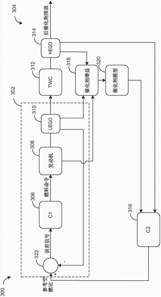
[0026] In order to reduce the lack of emissions, the catalyst can utilize oxygen storage materials, such as ceria in the form of cerium oxide, to provide a buffer for oxygen during rich or lean excursions. The air-fuel ratio entering the catalyst can be controlled so that the oxidation state of the catalyst is maintained at a desired level. In the example model of the present invention, the concentration of various exhaust types from the inlet to the outlet of the catalyst, such as H 2 , CO, NO x , HC and O 2 , Can be modeled using a simplified low-dimensional model. The model illustrates the composite catalyst dynamics, such as diffusion and reaction in the washcoat and catalyst aging, and reduces the dynamics to a set of axial average model equations. The model equation tracks the balance of each exhaust species in the liquid phase of the catalyst and the washcoat. In addition, the model compensates for the overall energy balance in the liquid phase of the catalyst and the w...


PUM


Abstract

Embodiments for an engine exhaust are provided. In one example, a method comprises adjusting a fuel injection amount based on a fractional oxidation state of a catalyst, the fractional oxidation state based on reaction rates of a plurality of exhaust gas species throughout a catalyst longitudinal axis and a set of axially-averaged mass balance and energy balance equations for a fluid phase and a washcoat of the catalyst. In this way, a simplified catalyst model may be used to control air-fuel ratio.

Description

Technical field [0001] The invention relates to feedback control of the air-fuel ratio in an internal combustion engine. Background technique [0002] Effective conversion of exhaust emissions in gasoline engines involves maintaining the catalyst intake air-fuel ratio within a narrow window around stoichiometry. However, during actual engine operation, a slight excursion away from stoichiometry may occur. In order to increase the operating window and thus improve the emission performance, the catalyst usually includes ceria in order to provide a buffer for oxygen storage. In order to maintain the best catalyst performance, through feedback control of the engine air-fuel ratio, the stored oxygen can be maintained at a desired set point based on engine load and temperature calibration. Summary of the invention [0003] However, the inventor of the present invention has recognized the problems of the above method. Determining the level of oxygen stored in a catalyst generally invo...

Claims


Application Information

Patent Timeline
Patent Type & Authority Applications(China)
IPC IPC(8): F01N11/00F02D41/02
CPCF01N11/007F01N2550/02F01N2560/025F01N2560/14F01N2900/1402F01N2900/1621F01N2900/1624F02D41/0235F02D41/0295F02D41/1441F02D41/1454F02D41/1456F02D41/1458F02D41/182F02D2200/0814F02D2200/0816Y02T10/12Y02T10/40F01N3/10F02D41/30
Inventor P·库马尔I·H·马基J·M·克恩斯M·J·于里克S·B·史密斯
Owner FORD GLOBAL TECH LLC
Why Eureka
Try Eureka