On-track space camera gain regulating method

A technology of a space camera and an adjustment method, which is applied in the direction of a photographic device, etc., can solve the problems of large difference in image grayscale, insufficient image layers, and overall dark image, and achieves the effects of high accuracy, high precision, and improved processing efficiency.

Active Publication Date: 2013-09-25
CHANGCHUN INST OF OPTICS FINE MECHANICS & PHYSICS CHINESE ACAD OF SCI
View PDF6 Cites 15 Cited by
  • Summary
  • Abstract
  • Description
  • Claims
  • Application Information

AI Technical Summary

Problems solved by technology

[0005] The present invention solves the problems that existing space cameras use fixed gain on orbit, which results in overall dark part of the image, poor image layers, low s...

Method used


Image

  • On-track space camera gain regulating method
  • On-track space camera gain regulating method
  • On-track space camera gain regulating method

Examples


specific Embodiment approach 1

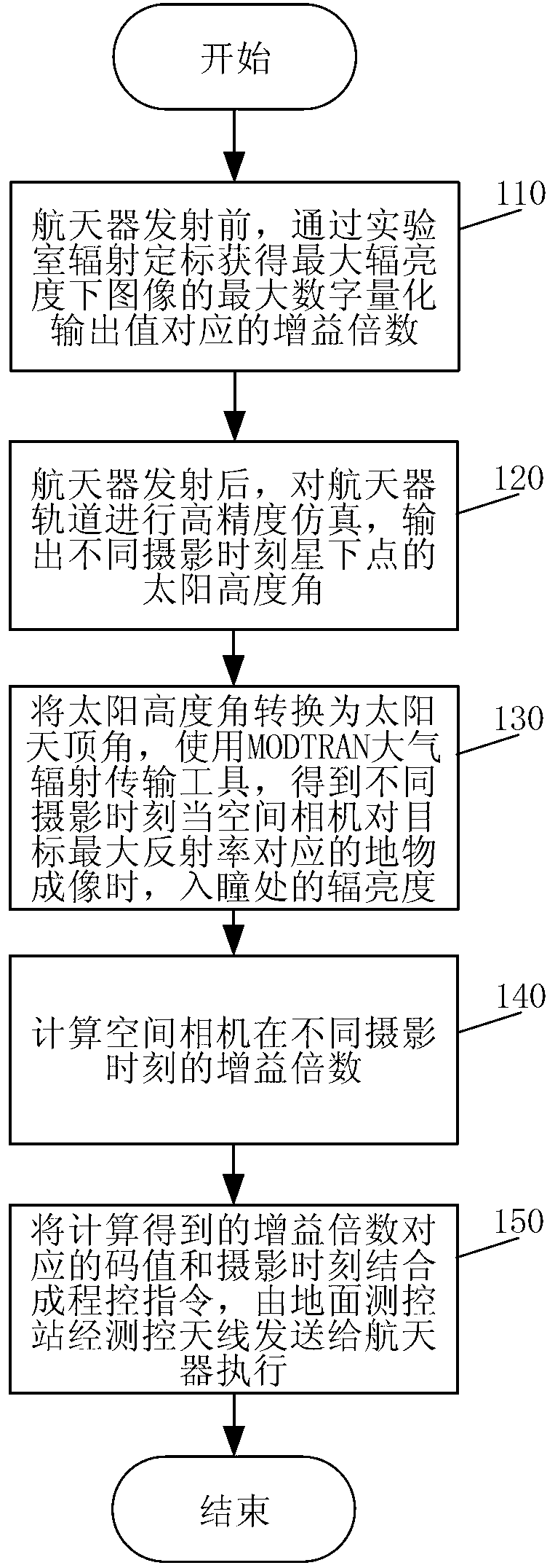
[0024] Specific implementation mode 1. Combination figure 1 and figure 2 Describe this embodiment, a method for adjusting the gain of a space camera on-orbit, the method is implemented by the following steps:

[0025] Step 1. Before the launch of the spacecraft, during the radiation calibration of the space camera laboratory, the maximum radiance L required by the user max Adjust the gain of the space camera down, so that the digital quantization output value of the image increases from small to the maximum value, and the gain multiple G corresponding to the maximum digital quantization output value of the image is obtained max ;

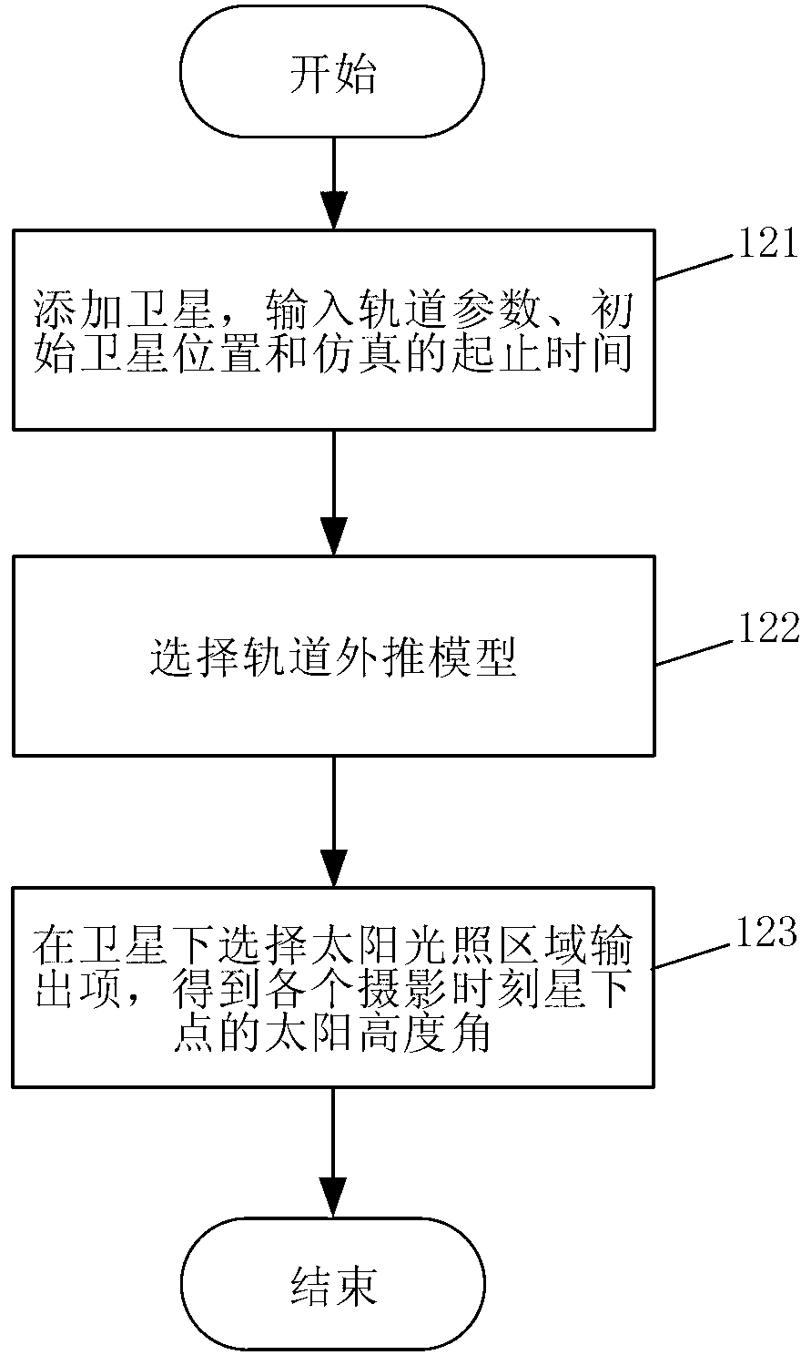
[0026] Step 2, after the spacecraft is launched, carry out high-precision simulation on the orbit of the spacecraft platform such as the satellite or the space station equipped with the space camera, and output the solar altitude angle of the sub-satellite point at different photography moments; the simulation adopts the STK simulation tool, and ...

specific Embodiment approach 2

[0036] Specific embodiment two, combine figure 1 and figure 2 This implementation mode is described. This implementation mode is an example of the on-orbit adjustment method for the space camera gain described in the first specific implementation mode. Through this example, the specific implementation process of the on-orbit adjustment method for the space camera gain is described in detail. In this embodiment, the wavelength range of the space camera is 510-690nm, and the maximum radiance L required by the user max 42.236W / m 2 ·sr, the target maximum reflectance required by the user is 0.5.

[0037] Step 110, before the launch of the spacecraft, set the radiance output by the integrating sphere and the maximum radiance L required by the user during the radiometric calibration of the space camera. max Same, that is 42.236W / m 2 · sr. Adjust the gain of the space camera so that the digital quantization output value of the image increases from small to the maximum value, and ...


PUM


Abstract

The invention discloses an on-track space camera gain regulating method, which relates to an on-track gain regulating method of a space camera for earth observation, and aims to the solve the problems that at present, a space camera adopts a fixed gain so as to lead to overall dimming of part of images, poor image gradation, low signal to noise ratio and the like. The regulating method comprises the following steps of: before a spacecraft is launched, acquiring a gain factor corresponding to the maximal digital quantification output value of images under maximal radiance through laboratory radiometric calibration; after the spacecraft is launched, simulating the track of the spacecraft with high accuracy, and outputting the solar altitude of sub-satellite points at different shooting time; converting the solar altitude into the solar zenith angle, thereby obtaining the radiance of an entrance pupil part by an MODTRAN atmospheric radiation transfer tool when the space camera forms images of a ground feature corresponding to the maximal object reflectivity at different time; calculating gain factors of the space camera at different shooting time; combining the code values corresponding to the gain factors obtained through calculation with the shooting time into a program control instruction, and sending the program control instruction from a ground measurement and control station to the spacecraft to execute through a measurement and control antenna.

Description

technical field [0001] The invention relates to a space camera for observing the earth by using a remote sensing satellite or a space station as a platform, in particular to an on-orbit adjustment method for the gain of the space camera. Background technique [0002] When the space camera is photographing the ground, there are significant differences in the reflectivity of ground objects, such as the reflectivity of sea water is about 0.05, while the reflectivity of ice and snow can reach up to 0.8. At the same time, the lighting conditions in different seasons and latitudes are different, resulting in large changes in the radiance at the entrance pupil of the space camera. In order to avoid the saturation of the target of interest in the remote sensing image acquired by the space camera and make it impossible to distinguish, the user requires the space camera to meet the maximum radiance requirement, that is, the output image under the maximum radiance condition is close to...

Claims


Application Information

Patent Timeline
IPC IPC(8): G01C11/02
Inventor 武星星刘金国周怀得余达
Owner CHANGCHUN INST OF OPTICS FINE MECHANICS & PHYSICS CHINESE ACAD OF SCI
Why Eureka
Try Eureka