Supercharge Your Innovation With Domain-Expert AI Agents!

Photoelectric detection control circuit

A technology of control circuit and photoelectric detection, which is applied in the direction of measurement circuit and photometry using electric radiation detectors, etc., which can solve the problems of self-excited oscillation of operational amplifiers, inconvenient actual use, and output voltage phase lag.

Inactive Publication Date: 2013-09-25
MAXPHOTONICS CORP
View PDF10 Cites 5 Cited by
  • Summary
  • Abstract
  • Description
  • Claims
  • Application Information

AI Technical Summary

Problems solved by technology

However, due to the inter-electrode distributed capacitance in photodetection, the operational amplifier also has input capacitance, and both the photodetector and the operational amplifier have inter-electrode capacitance distribution, these total capacitance and the feedback resistor R6 will form a hysteresis network, which will cause the output voltage Phase lag, easy to cause self-excited oscillation of the operational amplifier
[0004] In summary, the existing photoelectric detection control circuit obviously has inconvenience and defects in actual use, so it is necessary to improve it

Method used


Image

  • Photoelectric detection control circuit
  • Photoelectric detection control circuit

Examples


Embodiment Construction

[0017] In order to make the object, technical solution and advantages of the present invention clearer, the present invention will be further described in detail below in conjunction with the accompanying drawings and embodiments. It should be understood that the specific embodiments described here are only used to explain the present invention, not to limit the present invention.

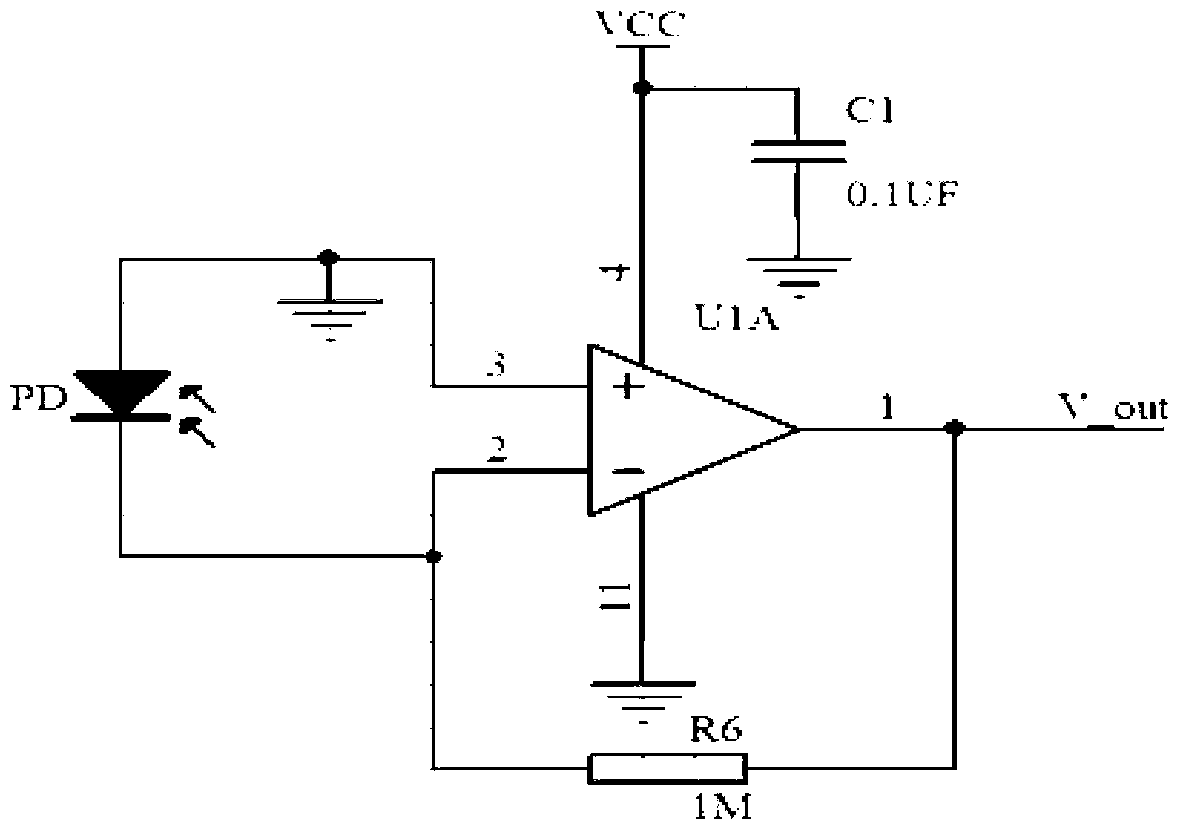
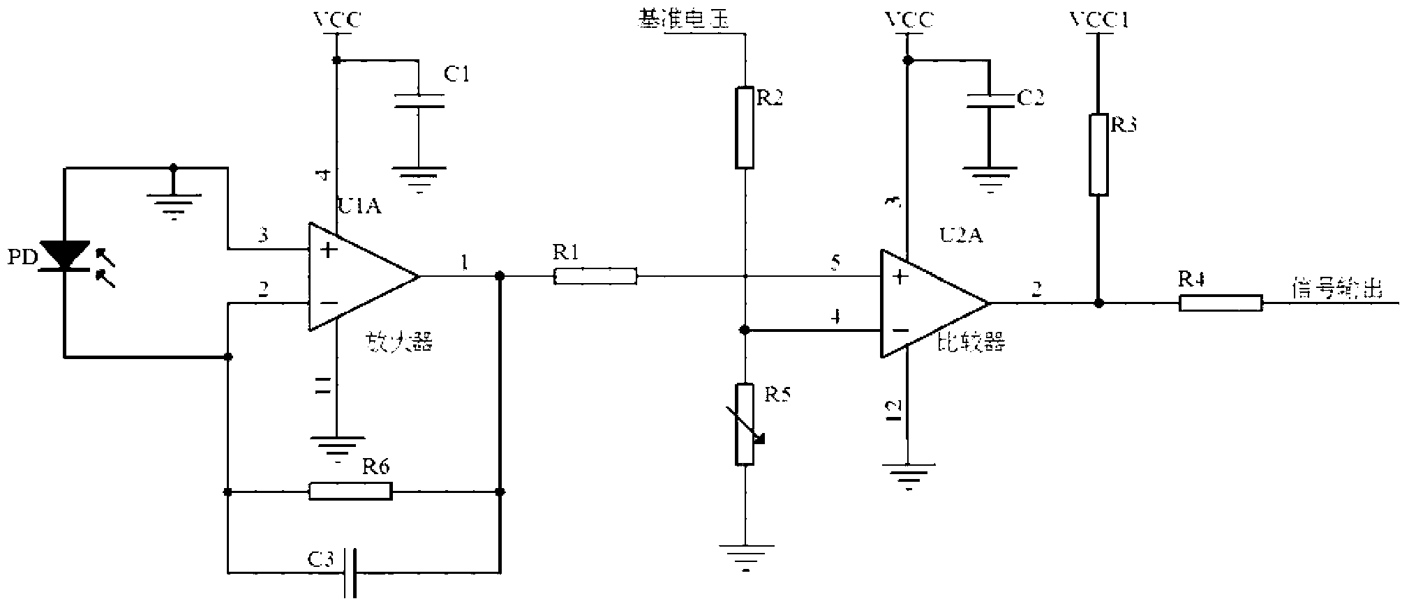
[0018] see figure 2 , the present invention provides a photoelectric detection control circuit, which includes a photoelectric converter PD, an operational amplifier U1A and a comparator U2A, wherein:

[0019] The two ends of the photoelectric converter PD are respectively connected to the non-inverting input terminal and the inverting input terminal of the operational amplifier U1A. The photoelectric converter PD can be a photodiode, which is used to convert the received optical signal into an electrical signal, and convert the electrical signal sent to op amp U1A for processing.

[0020] The o...


PUM


Abstract

The invention belongs to the technical field of photoelectricity and provides a photoelectric detection control circuit. The photoelectric detection control circuit comprises a photoelectric converter, an operational amplifier and a comparator, wherein the photoelectric converter is used for converting a received optical signal into an electric signal, the operational amplifier is used for amplifying the electric signal, a feedback resistor is connected between the inverted input end of the operational amplifier and the output end of the operational amplifier, the two ends of the photoelectric converter are connected with the normal input end of the operational amplifier and the inverted input end of the operational amplifier, the comparator is connected with the output end of the operational amplifier and is used for comparing electric signals output by the operational amplifier. Preferably, the two ends of the feedback resistor are connected with a compensation capacitor in parallel, and the compensation capacitor is used for phase compensation of the electric signals. Therefore, the photoelectric detection control circuit has the advantages that the stability of a circuit can be improved, a wide bandwidth range is kept, and conversion and comparison between the optical signal and the electric signal can be achieved quickly and accurately.

Description

technical field [0001] The invention relates to the field of photoelectric technology, in particular to a photoelectric detection control circuit. Background technique [0002] The photoelectric conversion circuit is a conversion bridge between basic physical quantities and electronic quantities. In the optical field that will continue to develop in the future, it is an indispensable part of photoelectric conversion. How to improve the conversion efficiency and accuracy is an important index for considering the photoelectric conversion circuit. [0003] Most of the existing conversion circuits adopt such as figure 1 The circuit structure shown is a photoelectric conversion method using a transconductance amplifier. However, due to the inter-electrode distributed capacitance in photodetection, the operational amplifier also has input capacitance, and both the photodetector and the operational amplifier have inter-electrode capacitance distribution, these total capacitance ...

Claims


Application Information

Patent Timeline
IPC IPC(8): G01J1/46
Inventor 胡小波黎永坚
Owner MAXPHOTONICS CORP
Features
  • R&D
  • Intellectual Property
  • Life Sciences
  • Materials
  • Tech Scout
  • Unparalleled Data Quality
  • Higher Quality Content
  • 60% Fewer Hallucinations
Learn More