A detection device and method for LED chips and devices
A technology of LED chips and detection devices, applied in the direction of single semiconductor device testing, etc., can solve the problems of restricting the cost of LED devices, the number of operations of the equipment mechanism, and the cost of capital, etc., to improve product cost competitiveness, good industrialization prospects, and reduce The effect of equipment wear
- Summary
- Abstract
- Description
- Claims
- Application Information
AI Technical Summary
Problems solved by technology
Method used
Image
Examples
Embodiment 1
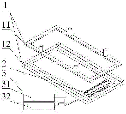
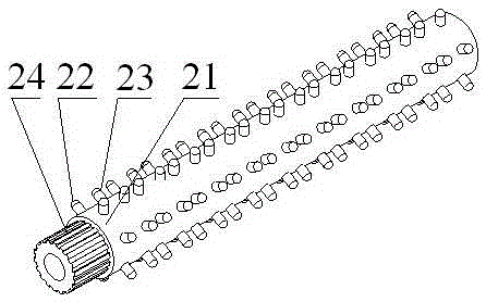
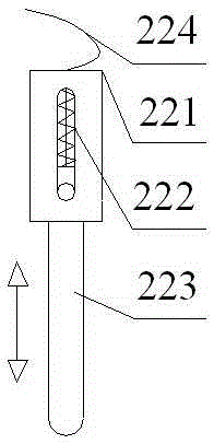
[0035] Such as Figure 1 to Figure 5 As shown, a detection device for LED chips and devices includes a square frame-shaped blue film or device substrate clamping fixture 1, a rotatable annular array test electrode roller 2 located under the blue film or device substrate clamping fixture 1 . Power supply and electrical parameter acquisition system 3, the annular array test electrode roller 2 includes a hollow cylindrical base 21 made of engineering plastics or bakelite, and the sides of the hollow cylindrical base 21 are evenly arranged in the axial and circumferential directions There are annular array through holes, and each annular array through hole is provided with an elastically stretchable metal test electrode extending outward. The metal test electrode includes a positive metal test electrode 22 and a negative metal test electrode 23. Each row of ring-shaped array through holes arranged in the axial direction of the hollow cylindrical base 21 is evenly spaced, and each ...
Embodiment 2
[0043] This implementation is different from Embodiment 1 in that the metal test electrode casing 221 is fixed on the hollow cylindrical base 21 in a threaded connection, and the threads are located on the outer surface of the metal test electrode sleeve 221 and in the annular array through holes of the hollow cylindrical base 21 On the surface, the protruding length of the metal test electrode can be adjusted by the number of turns of the screw thread, and this embodiment does not use an adjustment core.
Embodiment 3
[0045] The difference between this embodiment and Embodiment 1 is that the diameter of the inserted electrode length adjustment core 4 is 2 mm, the length of the test metal electrode protruding from the annular array test electrode roller 2 is 1 mm, the diameter of the probe needle 223 is 0.2 mm, and the tip distance 0.5 mm, and the distance between the positive metal test electrode 22 and the negative metal test electrode 23 is 2 mm, which is consistent with the distance between the positive and negative electrodes of a single LED device 51 to be tested. There are altogether 20 pairs of positive metal test electrodes 22 and negative metal test electrodes 23 in each row, and 12 pairs in total are evenly distributed around the annular array test electrode roller 2 . This embodiment is more suitable for applications where the size of the device is small and the arrangement density of the devices on the LED substrate is relatively high.
PUM
 Abstract
Description
Claims
Application Information
 - R&D
- Intellectual Property
- Life Sciences
- Materials
- Tech Scout
- Unparalleled Data Quality
- Higher Quality Content
- 60% Fewer Hallucinations
Browse by: Latest US Patents, China's latest patents, Technical Efficacy Thesaurus, Application Domain, Technology Topic, Popular Technical Reports.
© 2025 PatSnap. All rights reserved.Legal|Privacy policy|Modern Slavery Act Transparency Statement|Sitemap|About US| Contact US: help@patsnap.com


