
Digital slide real-time scanning automatic focus system and method

An automatic focusing and digital slicing technology, applied in installation, microscope, optics, etc., can solve problems such as image sharpness affecting focusing effect, reduced quality of digital slicing, mathematical model matching error, etc., to improve operation speed and simple algorithm. , cost saving effect

Inactive Publication Date: 2013-09-25
MOTIC CHINA GRP CO LTD
View PDF5 Cites 22 Cited by
  • Summary
  • Abstract
  • Description
  • Claims
  • Application Information

AI Technical Summary

Problems solved by technology

However, the disadvantage of this method is that the focal plane compensation of each field of view is determined according to the established focusing mathematical model. If the slice surface is complex, or various factors such as mechanical vibration during scanning cause slight changes in the hardware environment, All will affect the matching error between the mathematical model and the actual situation, resulting in an error in the estimated focal plane, thereby affecting the focusing effect and the clarity of the captured image, and reducing the quality of the scanned digital slice

Method used

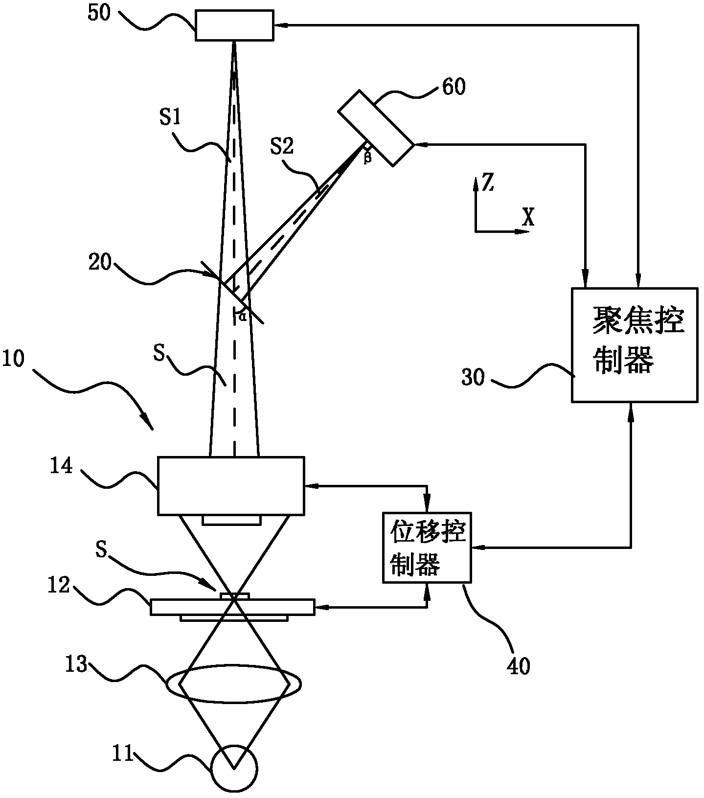
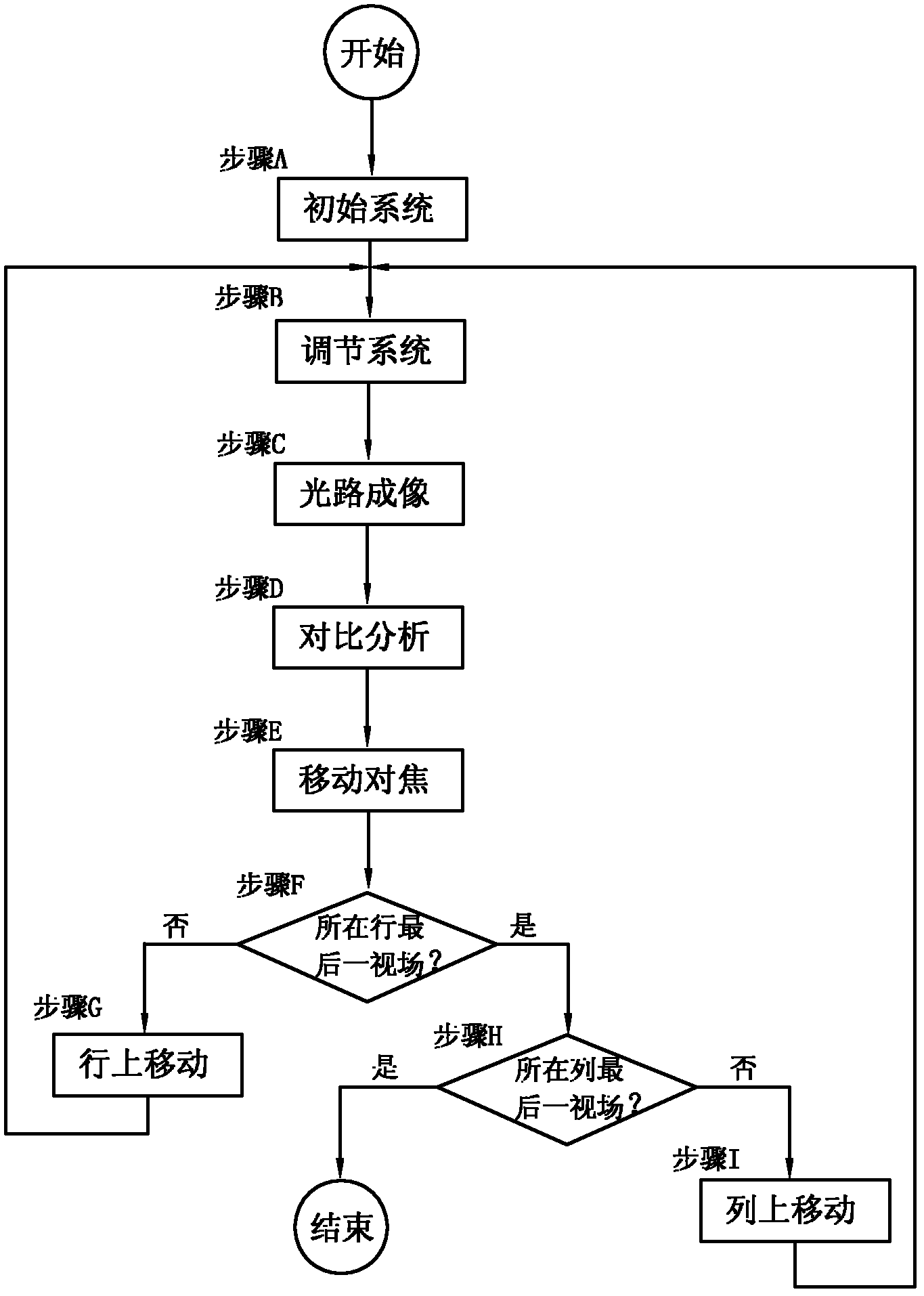

Image

  • Digital slide real-time scanning automatic focus system and method
  • Digital slide real-time scanning automatic focus system and method
  • Digital slide real-time scanning automatic focus system and method

Examples


Embodiment Construction

[0039] In order to make the technical problems, technical solutions and beneficial effects to be solved by the present invention clearer and clearer, the present invention will be further described in detail below in conjunction with the accompanying drawings and embodiments. It should be understood that the specific embodiments described here are only used to explain the present invention, not to limit the present invention.

[0040] In order to clearly illustrate the technical solution of the present invention, the technical terms are explained below:

[0041] Field of view: refers to the maximum range that the imaging device can observe, usually expressed in angles; the larger the field of view, the larger the observation range.

[0042] Common field of view: refers to the field of view range that can be observed by multiple imaging devices at the same time.

[0043] Depth of field: refers to the distance range of objects measured along the axis of the imaging depth of fie...


PUM


Abstract

The invention discloses a digital slide real-time scanning automatic focus system and method. The system comprises an optical microscope device, a dispersion prism, a focus controller, a displacement controller, a first imaging device and a second imaging device, wherein the focus controller adjusts the first imaging device and the second imaging device so that the first imaging device and the second imaging device can have a common view field. The dispersion prism splits a light path from the common view field into a first light path and a second light path. The first imaging device receives the first light path and forms a first image, and the second imaging device receives the second light path and forms a second image. The displacement controller estimates the position of a focus face of the next view field according to focus factor analyzing results of the two images of the current view field, and controls an object stage or an object lens to move to the next view field, so that the object stage or the object lens moves to the focus face of the next view field. According to the scheme, the digital slide real-time scanning automatic focus system is well compatible with a traditional optical microscope device, and repeated development is needless. Besides, the digital slide real-time scanning automatic focus system and method can obtain the best focus face quickly, and the obtained focus face is high in precision.

Description

technical field [0001] The invention relates to a digital slice real-time scanning automatic focusing system and an automatic focusing method. Background technique [0002] In the scanning of digital slices with an automatic microscope, the focus of the field of view is a very critical indicator, and its focusing effect directly affects the clarity of image imaging, which also directly affects the scanning quality of digital slices. [0003] Classical microscope autofocus uses several images captured at different z positions in a field of view, each image originates from a different z position, and then calculates the texture clarity of these several images at different z levels, also called the focus factor. The conventional method of calculating the focus factor is to use image edge detection, the greater the edge change, the sharper the image, so the greater the focus factor. The plane of the image corresponding to the largest focus factor is the best focus plane. This ...

Claims


Application Information

Patent Timeline
IPC IPC(8): G02B21/36G02B21/18G02B7/36
Inventor 贾守礼康军吴丹媛陈进
Owner MOTIC CHINA GRP CO LTD
Learn More