Under-voltage protection circuit and high-voltage integrated circuit

An undervoltage protection and circuit technology, applied in the field of circuits, can solve the problems of complex circuit design process, slow response time, and many components, and achieve the effects of simple design, faster response time, and fewer components used.

Active Publication Date: 2013-09-25
上海奔赛电子科技发展有限公司
View PDF6 Cites 7 Cited by
  • Summary
  • Abstract
  • Description
  • Claims
  • Application Information

AI Technical Summary

Problems solved by technology

[0006] In order to solve the problems of more components used in the undervoltage protection circuit in the prior art, slow response time, large power consumption and complicated circuit design process

Method used


Image

  • Under-voltage protection circuit and high-voltage integrated circuit
  • Under-voltage protection circuit and high-voltage integrated circuit
  • Under-voltage protection circuit and high-voltage integrated circuit

Examples


Embodiment 1

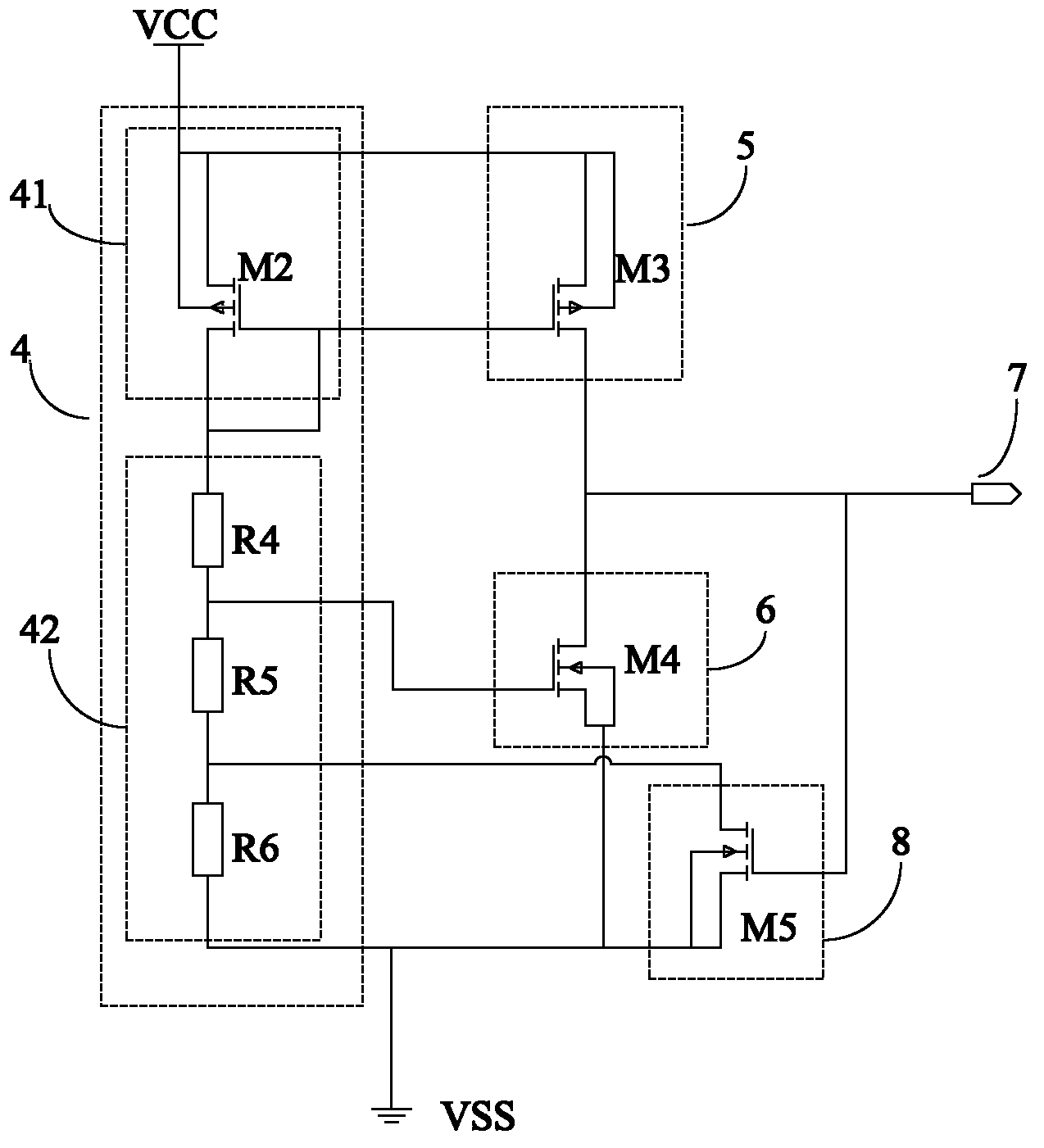
[0041] Such as figure 2As shown, the undervoltage protection circuit provided in this embodiment includes a voltage divider network 4, a pull-up circuit 5, an undervoltage protection signal output control switch 6, and an undervoltage protection signal output terminal 7. The voltage divider network 4 includes a driving power supply Sampling element 41 and voltage dividing element 42, described driving power sampling element 4 is connected with driving power VCC, is used for collecting driving power VCC; Described voltage dividing element 42 is connected with described driving power sampling element 41, is used for driving power The driving power supply VCC collected by the sampling element 41 is divided to output a second voltage signal to control the disconnection and conduction of the undervoltage protection signal output control switch 6; the pull-up circuit 5 is connected between the driving power supply and the Between the undervoltage protection signal output control sw...

Embodiment approach

[0042] As an implementation, the driving power sampling element 4 is a first MOS transistor M2, the substrate and source of the first MOS transistor M2 are connected to the driving power VCC, and the drain of the first MOS transistor M2 and the gate are respectively connected to the voltage dividing element 42; the first MOS transistor M2 is specifically a PMOS transistor (positive channel Metal Oxide Semiconductor, P-type metal oxide semiconductor transistor).

[0043] As an implementation, the voltage dividing element 42 includes a first resistor R4, a second resistor R5 and a third resistor R6 connected in series in sequence, and the first resistor R5 is respectively connected to the drain of the first MOS transistor M2 connected to the gate, the third resistor R6 is grounded, an output terminal connected to the undervoltage protection signal output control switch 6 is formed between the first resistor R4 and the second resistor R5, and is used to output the second voltage ...

Embodiment 2

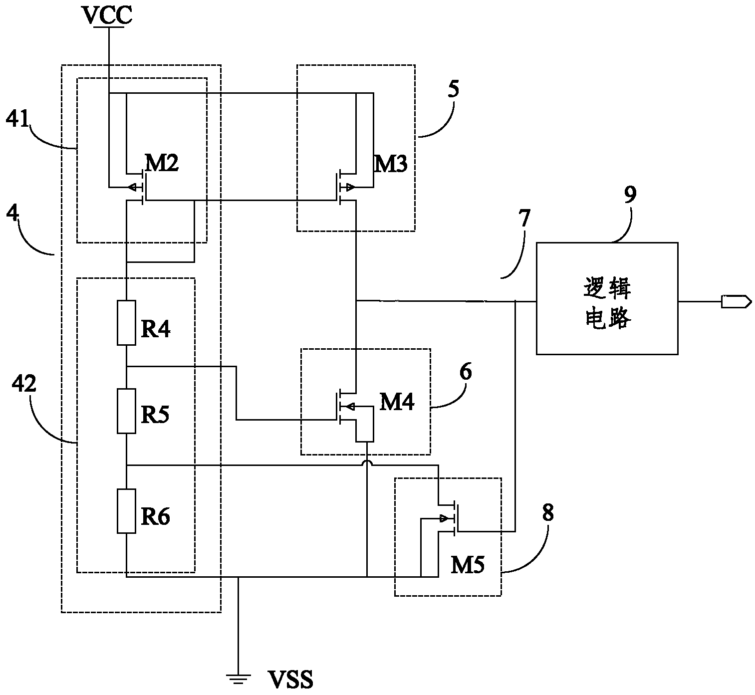
[0053] Such as Figure 7 As shown, the present invention also proposes a high-voltage integrated circuit, including a driving power supply 10, a plurality of electronic components 12, a control switch 11 and an undervoltage protection circuit 13; the driving power supply 10 is connected to the control switch 11 for providing work Power supply; the control switch 11 is connected to the plurality of electronic components 12 to control the operation of the plurality of electronic components 12; the undervoltage protection circuit 13 is connected to the driving power supply 10 and the control switch 11 respectively for driving The size of the power supply outputs an undervoltage protection signal to control the on and off of the control switch 11 .

[0054] The undervoltage protection circuit 13 is the undervoltage protection circuit described in Embodiment 1, and the driving power supply 10 is the driving power supply VCC described in Embodiment 1, which will not be described in ...


PUM


Abstract

The invention provides an under-voltage protection circuit for solving the problems that an under-voltage protection circuit is multiple in used component, slow in response and the like in the prior art. The under-voltage protection circuit comprises a potential-divider network, a pull-up circuit, an under-voltage protection signal output control switch and an under-voltage protection signal output end. The potential-divider network is used for conducting voltage dividing on a driving source to output second voltage signals so that the under-voltage protection signal output control switch can be controlled to be switched off and switched on. The pull-up circuit is connected between the driving source and the under-voltage protection signal output control switch, and the under-voltage protection signal output end is connected between the pull-up circuit and the under-voltage protection signal output control switch. When the under-voltage protection signal output control switch is switched off, the pull-up circuit pulls up under-voltage protection signals to be the driving source. When the under-voltage protection signal output control switch is switched on, the pull-up circuit pulls down the under-voltage protection signals to be low level signals. The used components of the under-voltage protection circuit are few. The invention further provides a high-voltage integrated circuit.

Description

technical field [0001] The invention relates to the field of circuits, in particular to an undervoltage protection circuit and a high-voltage integrated circuit. Background technique [0002] A high-voltage integrated circuit is a gate drive circuit with functions such as various protection circuits, low-voltage control circuits, and high-voltage power devices. It combines power electronics with semiconductor technology, which significantly improves the integration and stability of the whole machine. With the advantages of high integration density, small size, fast speed, and low power consumption, it gradually replaces traditional discrete devices, and is increasingly used in MOSFETs (Metal-Oxide-Semiconductor Field-Effect Transistor, Metal-Oxide-Semiconductor - Field Effect Transistor), IGBT (Insulated Gate Bipolar Transistor, Insulated Gate Bipolar Transistor) driving field. The core part of the high-voltage integrated circuit is the level shift circuit. The function of ...

Claims


Application Information

Patent Timeline
Patent Type & Authority Applications(China)
IPC IPC(8): H02H3/24
Inventor 高存旗刘杰张华群
Owner 上海奔赛电子科技发展有限公司
Why Eureka
Try Eureka