Clutch braking device, winding machine comprising device and operation method of winding machine

A technology of braking device and hoist, which is applied in the direction of brake actuator, combination of coupling and brake, clutch, etc., can solve the problems of complex system, high failure rate of pressure reducing valve, increased failure rate of hoist, etc. Production cost, improved safety, compact structure

Inactive Publication Date: 2013-10-02
钟发忠
View PDF8 Cites 5 Cited by
  • Summary
  • Abstract
  • Description
  • Claims
  • Application Information

AI Technical Summary

Problems solved by technology

[0003] In addition, because the pressure of the hydraulic system is very high during hoisting and hoisting, in order to protect the brakes of the hoist, a pressure relief valve needs to be specially configured to obtain a lower pressure to open the brakes. This pressure relief valve makes the system complicated, and the The failure rate of the pressure reducing valve is high, which leads to a significant increase in the failure rate of the hoist

Method used


Image

  • Clutch braking device, winding machine comprising device and operation method of winding machine
  • Clutch braking device, winding machine comprising device and operation method of winding machine
  • Clutch braking device, winding machine comprising device and operation method of winding machine

Examples


Embodiment Construction

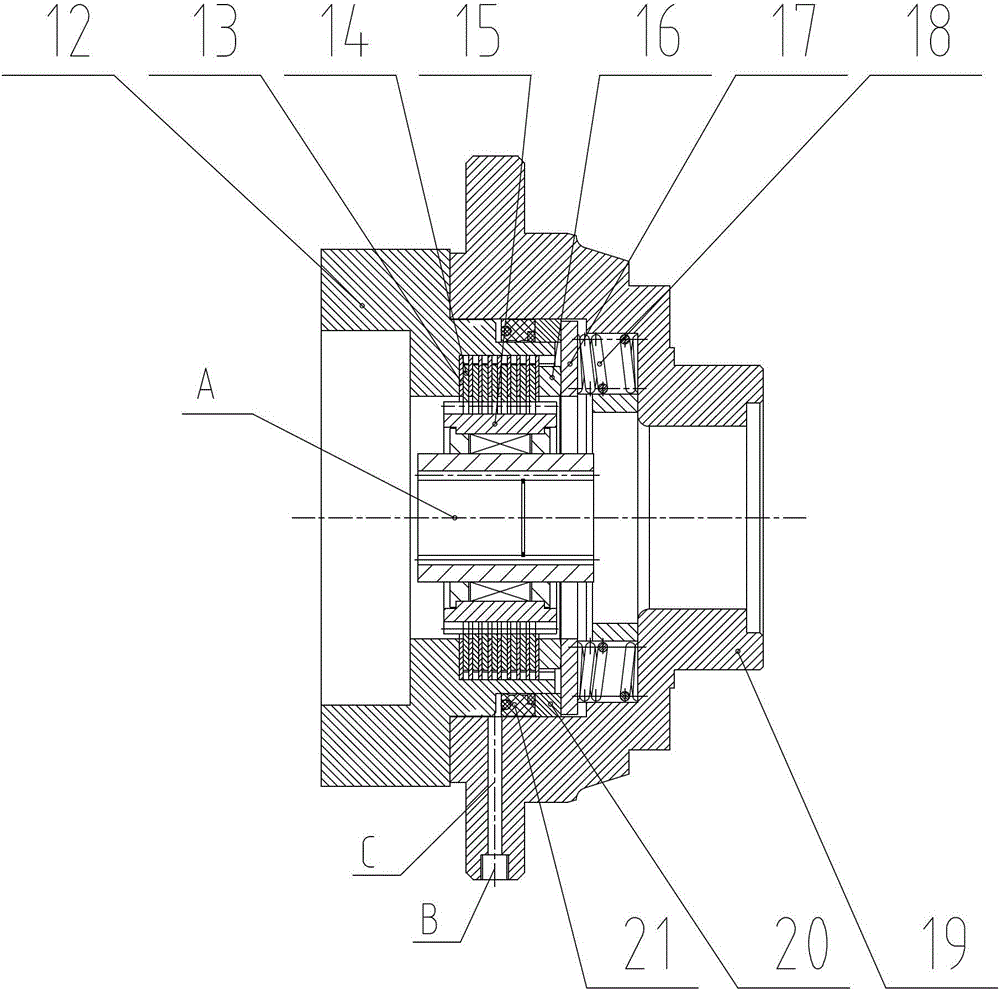
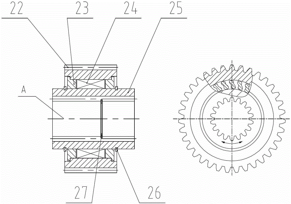
[0036] The following will be based on the attached Figure 1-3 And embodiment technical scheme of the present invention is described further.

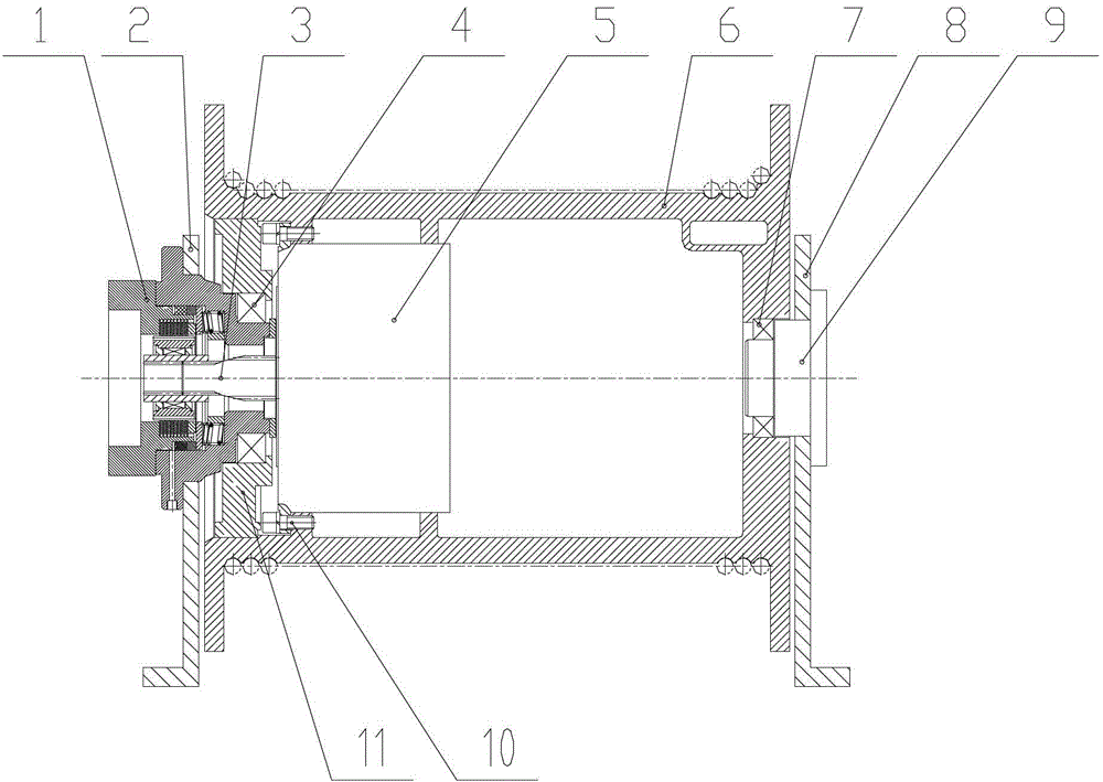
[0037] Such as figure 1 As shown, the winch of the present invention is mainly composed of a clutch brake device 1, a left bracket 2, an input shaft 3, a first bearing 4, a planetary reduction device 5, a reel 6, a second bearing 7, a bearing 8, and a support shaft 9 , bolts 10, support cover 11 and other components.

[0038] Both ends of the reel 6 are equipped with the first bearing 4 and the second bearing 7. The planetary reduction device 5 is placed inside the reel 6 and installed together with the reel 6 through bolts 10. The clutch brake device 1 and the left bracket 2 pass through The bolts are installed together and the reel 6 is supported by the first bearing 4, the support shaft 9 and the right bracket 8 are installed together by the bolt and the reel 6 is supported by the second bearing 7, and one end of the input shaft 3...


PUM


Abstract

The invention relates to a clutch braking device. The clutch braking device is characterized in that the clutch braking device (1) comprises a motor mounting seat (12), an internal tooth braking fixed plate (13), an external tooth braking moving plate (14), an overrun clutch assembly (15), a supporting ring (16), a pressing plate (17), a spring (18), a bearing seat (19), an annular piston (20) and a rubber seal ring (21). Meanwhile, the invention further provides a winding machine comprising the device and an operating method of the winding machine. Hook sliding of the winding machine is prevented during ascending or descending process safely and reliably through the setting of the overrun clutch assembly; and meanwhile, the interior of the winding machine creatively adopts the structure of the annular piston, so that the manufacturing technology of components and parts of a hydraulic system is simplified, the production efficiency is greatly improved, and the production cost is reduced.

Description

technical field [0001] The invention relates to a hoisting device, in particular to a clutch brake device, a hoist including the clutch brake device, and a hoist operating method. Background technique [0002] At present, the winches used in engineering cranes all need power to drive to realize the lifting and lowering of the mechanism. The hoist is usually equipped with a normally closed brake. Before the hoist is lifted or lowered, the normally closed brake must be opened by hydraulic oil pressure before the motor can drive the hoist. During the lifting process, when the winch stops and starts again, if the brake has been opened by the pilot pressure, but the main oil circuit pressure has not been able to drive the motor, due to the time difference, the lifting object will appear under the action of gravity. The phenomenon of sliding down by itself (or called sliding hook), is very dangerous. For example, the patent technology with the publication number CN102328886A and...

Claims


Application Information

Patent Timeline
Patent Type & Authority Applications(China)
IPC IPC(8): B66D5/14B66D5/28B66D1/00F16J15/06F16D41/06F16D67/04F16D65/22F16D121/06F16D125/06
Inventor 陈志武朱孝琼钟发忠胡昌国陈立
Owner 钟发忠
Why Eureka
Try Eureka