Process burner structure of gasification furnace

A technology of process burners and gasifiers, applied in the direction of granular/powdered fuel gasification, etc., can solve the problems of high heat flux density, non-stationary air flow, and large temperature gradient of cooling coils, so as to improve service life and reduce heat flow Density, the effect of reducing thermal stress

Active Publication Date: 2013-10-02
SINOPEC NINGBO ENG +2
View PDF12 Cites 12 Cited by
  • Summary
  • Abstract
  • Description
  • Claims
  • Application Information

AI Technical Summary

Problems solved by technology

However, there is great uncertainty in ensuring the long-term operation of the burner in this scheme. The main problem is that the airflow near the burner is not static. Although the injected water can vaporize and absorb heat, it does not only absorb the heat in the burner area. , In addition, the injection of water also has a certain impact on the composition of the syngas entering the gasifier, especially in the case of micro-holes, there is a large temperature gradient
[0006] The technical solutions disclosed by the patent No. CN201020534852.6 and the announcement No. CN101956982A all use spraying water through small holes to absorb heat, which also has the above problems, and because the heat flux density of the additionally introduced cooling coil itself is very large, there are also Cooling coils are also a major source of failure due to excessive thermal stress due to excessive temperature gradients

Method used


Image

  • Process burner structure of gasification furnace
  • Process burner structure of gasification furnace
  • Process burner structure of gasification furnace

Examples


Embodiment Construction

[0022] The present invention will be further described in detail below in conjunction with the accompanying drawings and embodiments.

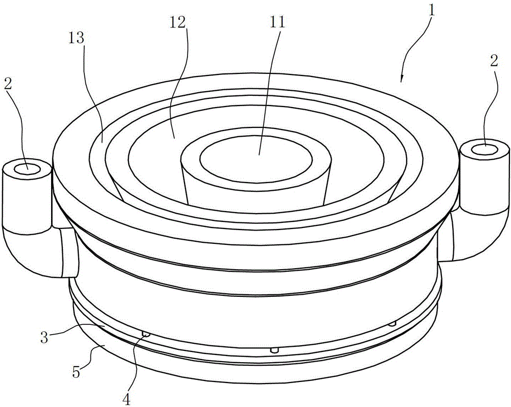
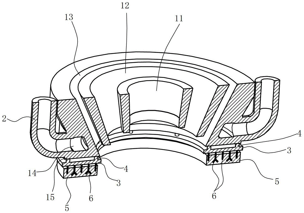
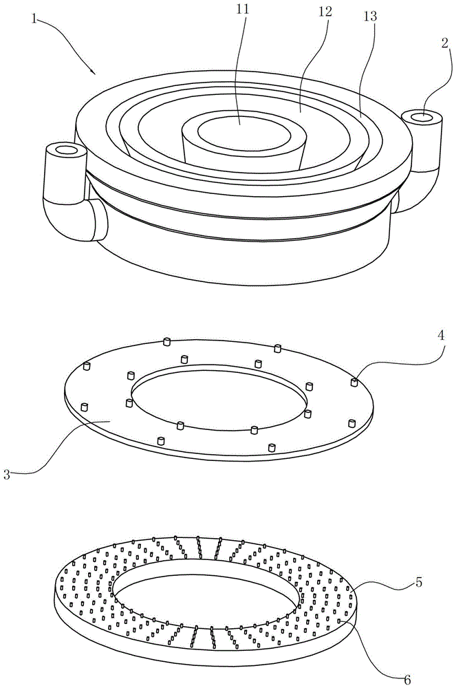
[0023] Such as Figure 1 to Figure 3 As shown, the process burner structure of the gasifier includes a burner body 1, on which there are pulverized coal channel 11, oxygen channel 12, steam channel 13 and cooling water connected with external water pipe 2 from inside to outside. Cavity 14.

[0024] The heat-shielding ring 3 is arranged in front of the front end face 15 of the burner, and the heat-shielding ring 3 is welded on the front end face of the burner through a plurality of connecting nails 4 arranged at intervals. The heat-shielding ring in this embodiment is made of N06600 material, the size of the through hole in the middle of the heat-shielding ring is equal to the diameter of the steam channel 13, and the thickness of the heat-shielding ring is 2 mm. The connecting nail 4 is made of N06600 material, one end of the connecting nail...


PUM

PropertyMeasurementUnit
flame retardantaaaaaaaaaa

Abstract

The invention relates to a process burner structure of a gasification furnace. The process burner structure comprises a burner body, wherein a plurality of material channels and cooling water cavities are orderly arranged on the body from inside to outside. The process burner structure is characterized in that a thermal insulating layer, which is matched with the front end face of the burner, and of which the refractoriness is greater than or equal to 1770 DEG C, is arranged at the front end face of the burner; the thermal insulating layer is parallel to the front end face of the burner and connected with the front end face of the burner through a plurality of slag nails which are arranged at intervals. Compared with the prior art, conventional ideas of prolonging the service life of the burner in the field and providing the operating cycle are avoided; the density of heat flow through the front end face of the burner body is greatly reduced by providing the thermal insulating layer to prevent high-temperature radiation inside the gasification furnace. Thus, thermal stress caused by temperature gradient near the front end face is greatly reduced; meanwhile, the temperature of the front end face of the burner can be reduced; the allowable stress of the burner is increased; the operating cycle of the process burner of the gasification furnace is effectively prolonged.

Description

technical field [0001] The invention relates to a gasification furnace structure, in particular to a gasification furnace process burner structure. Background technique [0002] The burner is one of the key components of the gasification furnace. Its main function is to introduce fuel and gasification agent into the gasification furnace at a certain speed. A chemical reaction in which incomplete combustion occurs after mixing. Since the working temperature in the gasifier is usually higher than 1400°C and it is in a pressurized environment, the requirements for the burner are very high. If the structure of the burner is not properly designed, the mixing effect of the fuel and the gasification agent will be poor, Insufficient cooling at the end of the burner and excessive thermal stress will affect the normal operation of the gasifier in severe cases. [0003] In order to increase the operating cycle of the burner and prevent the burner from cracking under stress, people ha...

Claims


Application Information

Patent Timeline
Patent Type & Authority Applications(China)
IPC IPC(8): C10J3/50
Inventor 费名俭郭文元蒋自平陈央屠宏斌周永康
Owner SINOPEC NINGBO ENG
Why Eureka
Try Eureka