Ground current isolator for radio frequency signals

A technology of radio frequency signal and ground current, applied in the direction of circuits, electrical components, waveguide devices, etc., can solve the problems of complex assembly process, high precision, and low production efficiency, and achieve simple assembly process, good high-frequency performance, and simple structure Effect

Inactive Publication Date: 2013-10-02
STATE GRID GASU ELECTRIC POWER RES INST +1
View PDF3 Cites 2 Cited by
  • Summary
  • Abstract
  • Description
  • Claims
  • Application Information

AI Technical Summary

Problems solved by technology

[0009] The present invention provides a radio frequency signal ground current isolator with simple structure, simple assembly process, high production efficiency and low cost; it solves the problem of complex structure of the isolator in the prior art, complex assembly process, high precision required, Technical problems of low production efficiency and high cost

Method used


Image

  • Ground current isolator for radio frequency signals
  • Ground current isolator for radio frequency signals
  • Ground current isolator for radio frequency signals

Examples


Embodiment 1

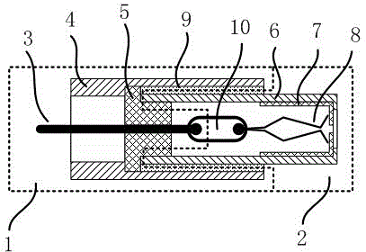
[0025] Such as figure 1 As shown, a radio frequency signal ground current isolator includes a first coaxial connector 1 and a second coaxial connector 2, the first coaxial connector 1 is formed by a first shielding layer 4 and is located on the first shielding layer 4 The second coaxial connector 2 is composed of the second shielding layer 6 and the second insulator 7 and the retaining spring 8 located in the second shielding layer 6 .

[0026] The axial section of the first insulator 5 is "T" shape, one end of the first insulator 5 abuts against the shoulder on the inner wall of the first shielding layer 4, and the outer peripheral surface of the first shielding layer 4 is smooth. The second shielding layer 6 is cylindrical, one end of the second shielding layer 6 abuts against the step of the first insulator 5, and there is a flanging inward at the other end of the second shielding layer 6, and the end of the second insulator 7 It abuts against the flange of the second shie...

Embodiment 2

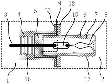
[0031] like figure 2 As shown, the difference from Embodiment 1 is that a first annular flange 11 is integrally formed at one end of the first shielding layer 4, and a second annular flange 11 is integrally formed at one end of the second shielding layer 6 close to the first coaxial connector. Ring flange 12, the first ring flange 11 and the second ring flange 12 are parallel to each other, the outer diameter of the first ring flange 11 is the same as the outer diameter of the second ring flange 12, between the end faces of the two flanges There is a gap 9 between them, the gap 9 is circular, and the outer diameter of the gap 9 is the same as that of the first ring flange 11 and the second ring flange 12 . The opening direction of the gap 9 is along the radial direction of the first shielding layer 4, and the gap 9 is filled with a dielectric material of high dielectric constant epoxy, and the dielectric material is filled from the radial direction, and the filling process is...

Embodiment 3

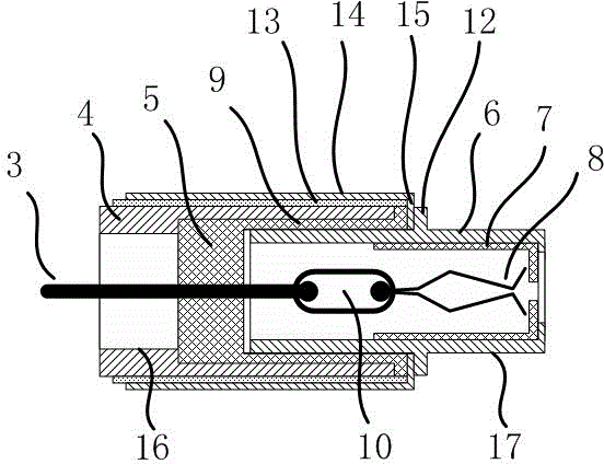
[0034] like image 3 As shown, the difference from Embodiment 1 is that the first shielding layer 4 is cylindrical and has a shoulder on its inner wall, and the second shielding layer 6 has a second annular flange 12 integrally formed in the middle. The first insulator 5 is filled in the gap 9, that is, the first insulator 5 is extended into the gap 9, the first insulator 5 has an annular outer flange, and the outer diameter of the outer flange is equal to the first shielding layer 4, That is to say, the end of the first shielding layer 4 abuts on the outer edge of the first insulator 5 , and the outer peripheral surface of the outer edge of the first insulator 5 is flush with the outer peripheral surface of the first shielding layer 4 . Then the insulating film 13 is wound on the outer peripheral surface of the first shielding layer, and the metal foil 14 is wound on the outer peripheral surface of the insulating film 13, and the insulating film 13 wraps the outer peripheral ...


PUM


Abstract

The invention relates to an isolator which obstructs DC signals and low-frequency signals and allows passing of radio frequency signals. The ground current isolator of the radio frequency signals comprises a first coaxial connector and a second coaxial connector which are connected with each other. A first insulator of the first coaxial connector is located in a first shielding layer, and a second insulator of the second coaxial connector is located in a second shielding layer. One end of the second shielding layer has an intersected superposed segment with the first shielding layer. The superposed segment between the first shielding layer and the second shielding layer is provided with a clearance which is internally provided with a conductive medium layer. The ground current isolator for the radio frequency signals provided by the invention is simple in structure simple in assembly process, high in production efficiency and low in cost. The ground current isolator settles the technical problems in the prior-art isolator such as complicated structure, difficult assembling process, high precision requirement, low production efficiency and higher cost.

Description

technical field [0001] The invention relates to an electronic component, in particular to an isolator capable of blocking direct current and low frequency signals and passing radio frequency signals. Background technique [0002] The cable TV network connects the set-top boxes or TVs of every household through cables. There may be inconsistencies in ground potential between users and between users and cable TV transmission equipment, which will generate ground loop circulation in the cables, causing the cables to heat up. The equipment is damaged, which may cause a fire in severe cases. [0003] Use the RF signal ground loop isolator (hereinafter referred to as the isolator) to cut off the ground loop current and prevent accidents. This type of isolator is usually implemented by two coaxial connectors and several capacitors, and the grounds of the two coaxial connectors are connected by capacitors. Hundreds to thousands of pF capacitors have low impedance to 48MHz-950MHz c...

Claims


Application Information

Patent Timeline
Patent Type & Authority Applications(China)
IPC IPC(8): H01P1/36H01R24/40H04N7/10
Inventor 温志伟马呈霞李君
Owner STATE GRID GASU ELECTRIC POWER RES INST
Why Eureka
Try Eureka