Rotating push processing device with stroke control function

A stroke control and processing device technology, which is applied in the direction of thread cutting devices, manufacturing tools, metal processing equipment, etc., can solve problems such as high energy consumption, potential safety hazards for operators, and large mechanical wear, and achieve low energy consumption and safety. High, low mechanical wear effect

Inactive Publication Date: 2013-10-09
WUHU AOBENMA AUTOMOBILE PARTS
View PDF6 Cites 10 Cited by
  • Summary
  • Abstract
  • Description
  • Claims
  • Application Information

AI Technical Summary

Problems solved by technology

[0003] In the prior art, the rotary propulsion processing device is generally not equipped with a stroke control mechanism, but the purpose of adjusting the movement stroke of the actuator is achieved by increasing the stroke distance of the actuator; during the stroke adjustment process, the actuator moves up and down At the same time, the rotary motion is also performed, that is, the stroke adjustment process is also a rotary propulsion process. Therefore, the work energy consumption of the stroke adjustment is relatively large, and the mechanical wear is relatively large. Moreover, during the stroke adjustment process, the rotary motion of the actuator has a negative impact on the operator. Bigger security risk

Method used


Image

  • Rotating push processing device with stroke control function

Examples


Embodiment Construction

[0021] The technical solutions of the present invention will be further described below in conjunction with the accompanying drawings and through specific implementation methods.

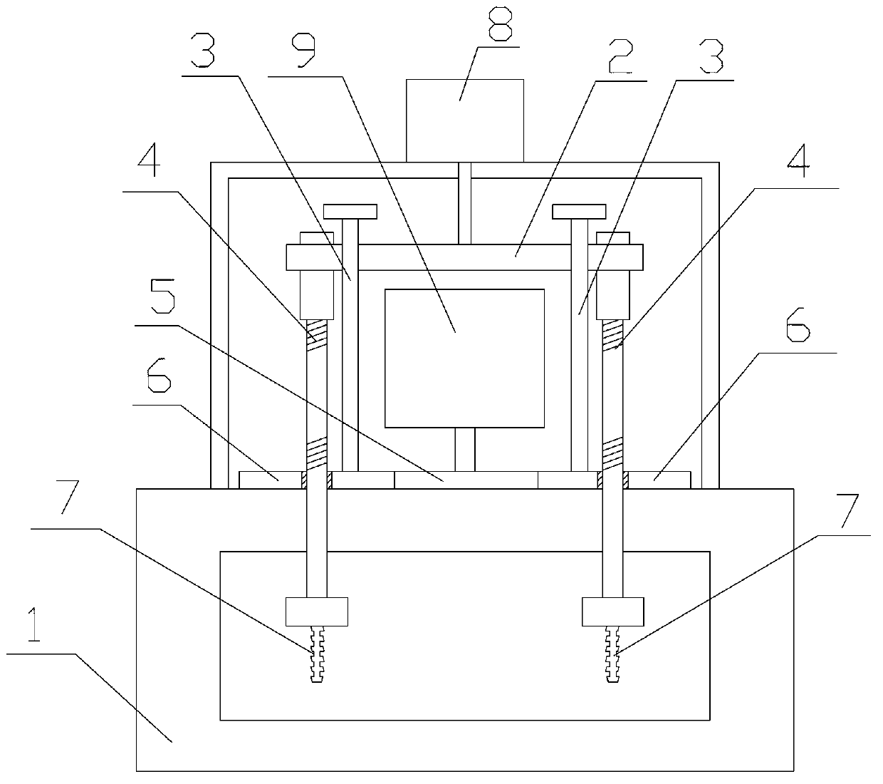
[0022] like figure 1 as shown, figure 1 It is a schematic structural diagram of a stroke-controlled rotary propulsion processing device proposed by the present invention.

[0023] refer to figure 1 , a stroke-controlled rotary propulsion processing device proposed by the present invention includes: a bracket 1, a stroke plate 2, a plurality of guide posts 3, a plurality of screws 4, a driving gear 5, a plurality of driven gears 6, and a plurality of execution components 7. The first driving mechanism 8 and the second driving mechanism 9, wherein:

[0024] A plurality of guide columns 3 are arranged in parallel and fixed on the bracket 1, the travel plate 2 passes through the plurality of guide columns 3, the first drive mechanism 8 is fixed on the bracket 1 and connected with the travel plate 2, ...


PUM


Abstract

The invention provides a rotating push processing device with a stroke control function. The upper ends of a plurality of threaded rods are connected with a stroke flat plate in a threaded mode, the threaded rods penetrate through a plurality of driven gears respectively, the middle of each threaded rod can be connected with each driven gear in a threaded mode, a plurality of execution parts are fixed at the lower ends of the threaded rods respectively, a first driving mechanism drives the stroke flat plate to move up and down to carry out stroke adjustment, the middle of each threaded rod and each driven gear are in a threaded connection state when the stroke flat plate is at the preset position, and a second driving mechanism drives a driving gear, drives the driven gears to rotate, and further drives the threaded rods to carry out synchronous downward rotating push so as to carry out processing operation. According to the rotating push processing device with the stroke control function, a stroke control mechanism is arranged in the rotating push processing device to carry out stroke adjustment on an execution mechanism, the execution mechanism only carries out vertical linear movement and does not carry out rotating movement in the process of stroke adjustment, and compared with the prior art, the rotating push processing device with the stroke control function is low in working energy consumption of stroke adjustment, low in mechanical wear and high in safety.

Description

technical field [0001] The invention relates to the technical field of rotary propulsion processing tooling, in particular to a stroke-controlled rotary propulsion processing device. Background technique [0002] At present, in the large-scale and industrialized parts manufacturing process, it is required to complete the production and molding of multiple parts in one processing operation process. Generally, it is necessary to set up multiple actuators, for example, in the drilling and tapping process of parts In the process, by setting multiple drill bits or tapping heads, in one process flow, multiple drill bits or tapping heads are lowered and rotated synchronously to process the workpiece, and the drilling and tapping operations of multiple parts are completed at one time. [0003] In the prior art, the rotary propulsion processing device is generally not equipped with a stroke control mechanism, but the purpose of adjusting the movement stroke of the actuator is achieve...

Claims


Application Information

Patent Timeline
Patent Type & Authority Applications(China)
IPC IPC(8): B23B39/16B23B47/06B23B47/18B23B47/30B23G1/20B23G1/44
Inventor 林振杰
Owner WUHU AOBENMA AUTOMOBILE PARTS
Why Eureka
Try Eureka