Manufacturing method for high-pressure tank, and high-pressure tank

A manufacturing method and technology of high-pressure tanks, applied in the field of high-pressure tanks, to achieve the effects of extending cruising range, reducing size, and reducing costs

Active Publication Date: 2013-10-09
TOYOTA JIDOSHA KK
View PDF6 Cites 14 Cited by
  • Summary
  • Abstract
  • Description
  • Claims
  • Application Information

AI Technical Summary

Problems solved by technology

[0005] However, there is room for improvement in the techniques described in JP-A-2008-45660, JP-A-2004-293571, and JP-A-8-216277 in terms of reliability, ie, pressure resistance and durability, of high-pressure tanks

Method used


Image

  • Manufacturing method for high-pressure tank, and high-pressure tank
  • Manufacturing method for high-pressure tank, and high-pressure tank
  • Manufacturing method for high-pressure tank, and high-pressure tank

Examples


Embodiment Construction

[0030] Hereinafter, embodiments of the present invention will be described with reference to the accompanying drawings.

[0031] A. Structure of high pressure tank

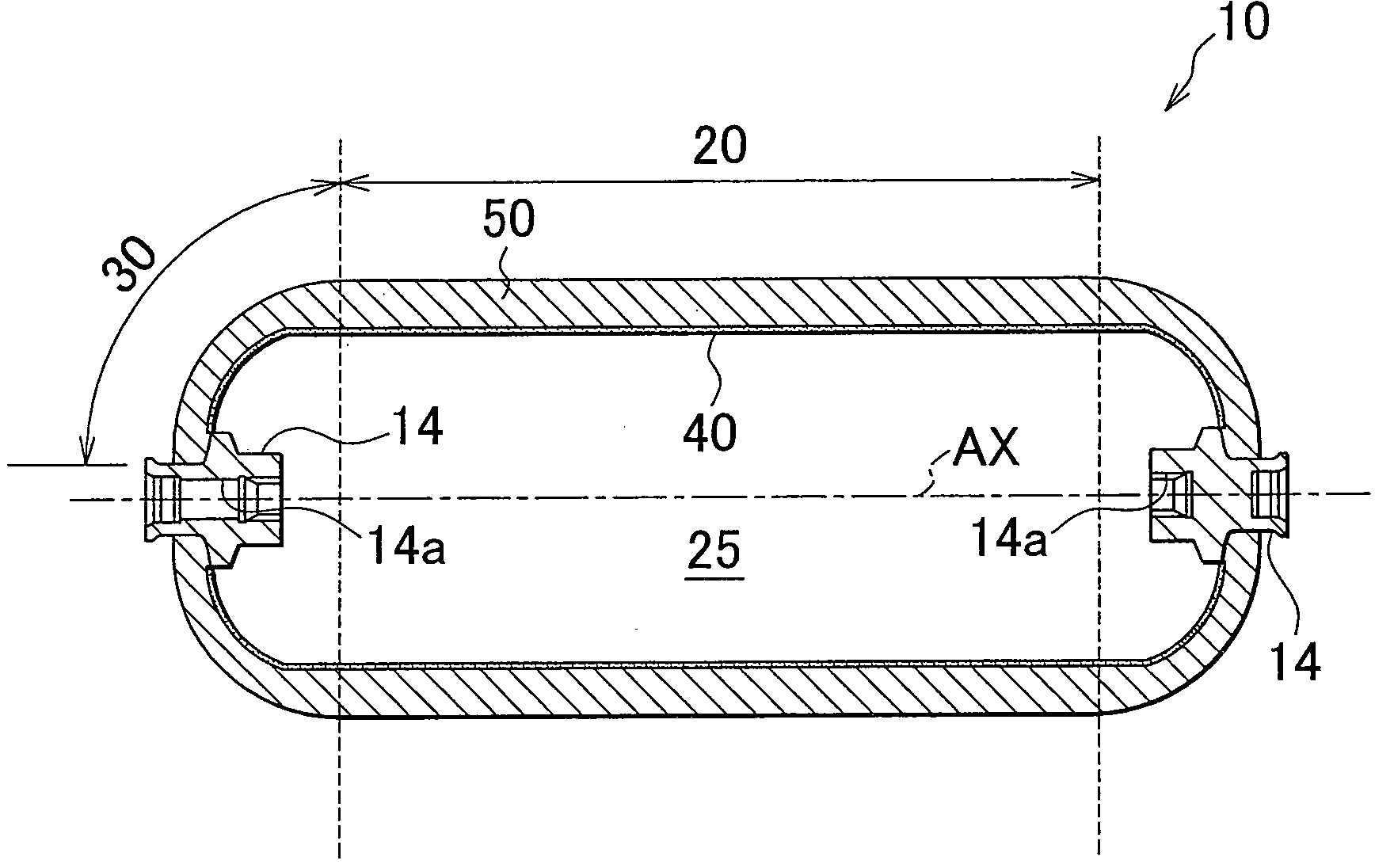
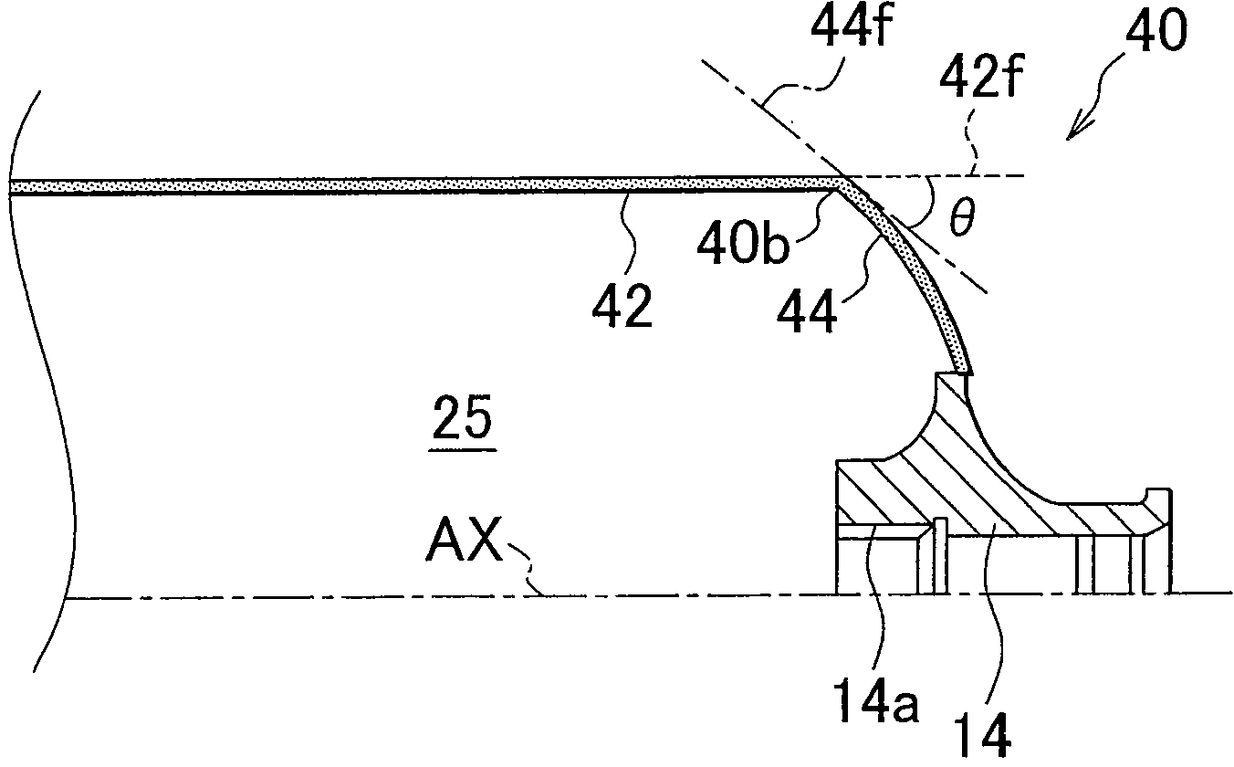
[0032] Figure 1A and Figure 1B is a view illustrating a schematic configuration of the high-pressure tank 10 according to the embodiment of the present invention. Figure 1A A cross-sectional view of the high pressure tank 10 is shown. in addition, Figure 1B Shows Figure 1A A partially enlarged view of . Note that in Figure 1B In , illustration of the fiber-reinforced plastic layer 50 (to be described later) is omitted.

[0033] as in Figure 1A As shown in , a high pressure tank 10 includes a liner 40 , a fiber reinforced plastic layer 50 and two end fittings 14 . A fiber reinforced plastic layer 50 covers the surface of the liner 40 . Each end fitting 14 has an opening 14a. Note that in the present embodiment, the high-pressure tank 10 includes two end fittings 14 ; alternatively, the high-pressure t...


PUM


Abstract

A step of forming a low-angle helical layer on an outer surface of at least part of each liner dome portion and an outer surface of a liner cylindrical portion, a step of forming an inner hoop layer on an outer surface of the low-angle helical layer on the liner cylindrical portion, and a step of forming a mixed layer by alternately laminating a low-angle helical layer and an outer hoop layer on an outer surface of the inner hoop layer and low-angle helical layer on each liner dome portion. Then, on the liner cylindrical portion, 90% or more of the sum of the thickness of the inner hoop layer and the thickness of the outer hoop layer in the mixed layer is arranged within the range of 75% of the fiber reinforced plastics layer adjacent to the liner in a thickness direction of the fiber reinforced plastics layer.

Description

technical field [0001] The invention relates to a manufacturing method for a high-pressure tank and a high-pressure tank. Background technique [0002] In recent years, a vehicle has been developed that is driven by energy upon combustion of fuel gas or electric energy generated by an electrochemical reaction of fuel gas. Such vehicles may be equipped with high-pressure tanks that store fuel gases such as natural gas and hydrogen. In this case, in order to reduce the size of the high-pressure tank in consideration of the mountability of the high-pressure tank on the vehicle when extending the cruising range of the vehicle, it is required to fill the high-pressure tank with fuel gas at a higher filling pressure. [0003] In order to fill the high-pressure tank with fuel gas at a high filling pressure, it is necessary to increase the strength of the high-pressure tank. Then, as a technique for increasing the strength of a high-pressure tank, there is known a technique of for...

Claims


Application Information

Patent Timeline
Patent Type & Authority Applications(China)
IPC IPC(8): B29C70/22B29C70/32B29C53/56B29C53/58B29C53/60F17C1/16
CPCB29D22/003Y02E60/321B29C70/222B29L2031/7156F17C1/16B29C53/562B29C63/24B29C53/602B29C53/58B29C70/32F17C1/00F17C2201/0109F17C2201/056F17C2201/058F17C2203/0619F17C2203/0643F17C2203/0646F17C2203/066F17C2203/0665F17C2203/067F17C2205/0397F17C2209/2154F17C2209/232F17C2221/012F17C2221/033F17C2223/0123F17C2223/036F17C2260/011F17C2270/0168Y02E60/32F17C1/04B32B1/02B32B1/00F17C1/06
Inventor 大坪弘和西部志朗
Owner TOYOTA JIDOSHA KK
Why Eureka
Try Eureka