
Power takeoff transmission shaft cold precision forging plastic forming process

A technology of plastic molding and transmission shaft, which is applied in the direction of manufacturing tools and other manufacturing equipment/tools, etc., can solve the problems of large investment in machining equipment, waste of raw materials, and long production cycle, so as to reduce manufacturing cost and production cycle, and meet product requirements. The effect of precision requirements and simple processing methods

Active Publication Date: 2013-10-16
江苏威鹰机械有限公司
View PDF8 Cites 24 Cited by
  • Summary
  • Abstract
  • Description
  • Claims
  • Application Information

AI Technical Summary

Problems solved by technology

Disadvantages of hot forging of PTO drive shaft: loose structure, low density; low strength, high labor intensity; low efficiency, long production cycle; difficult deep hole processing and high cost; large investment in machining equipment; waste of raw materials

Method used


Image

  • Power takeoff transmission shaft cold precision forging plastic forming process
  • Power takeoff transmission shaft cold precision forging plastic forming process
  • Power takeoff transmission shaft cold precision forging plastic forming process

Examples


Embodiment 1

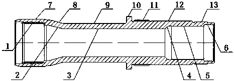
[0025] Embodiment one: see figure 1 As shown, a transmission shaft of a power take-off includes a hollow shaft body and has an inner circle and an outer circle. The inner circle has a splined inner circle surface 1, an inner diameter shrinkage transition surface 2, and a shrinkage inner circle surface 3 connected in sequence. , an inner diameter expansion transition surface 4, an expansion inner circle surface 5 and a large aperture inner circle surface 6; the outer circle has an outer circle surface 7 connected in sequence, an outer diameter contraction transition surface 8, a contraction outer circle surface 9, and an annular bump 10. The outer circular surface 11 of straight teeth, the second outer circular surface 12 and the outer diameter shrinkage thread surface 13; the inner circular surface 1 of the spline corresponding to the outer circular surface 7 is arranged on the inner circle of the hollow shaft body, and the annular convex The block 10 and the spur outer circul...

Embodiment 2

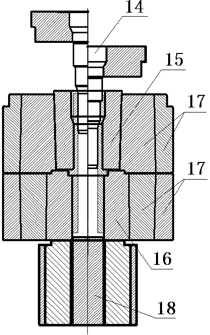
[0032] Embodiment two: same as embodiment one, the only difference is that the upper die 15 is provided with an annular groove cavity 20 on the inner wall of the joint, and the annular groove cavity 20 is connected to the outer circle of the power take-off drive shaft. The ring bump 10 matches.

Embodiment 3

[0033] Embodiment three: same as embodiment one, the only difference is that the upper die 15 and the lower die 16 are combined to be provided with an annular groove cavity 20 on the inner wall of the joint, and the annular groove cavity 20 is connected with the power take-off The annular protrusion 10 on the outer circle of the transmission shaft matches.


PUM


Abstract

The invention discloses a power takeoff transmission shaft cold precision forging plastic forming process which comprises the following steps: a, cutting out bar materials, conducting extrusion pretreatment, b, conducting deep hole extrusion and punching, c, conducting forward extrusion, d, conducting reducing and extrusion, e, conducting plasticity chambering internal spline extrusion, f, conducting rolling extrusion, and cold forging a blank which basically conforms to the size of a transmission shaft of a power takeoff in a mold. Forging and demolding are convenient, and then the blank is machined through a machine tool. The machining method is simple, the structure is fine, the strength is high, the production efficiency is high, raw materials are saved, the requirements for product precision of the transmission shaft of the power takeoff are met, the manufacturing cost and the production cycle are reduced, and meanwhile the power takeoff transmission shaft cold precision forging plastic forming process also conforms to the tendency of the development of the present world manufacturing industry.

Description

technical field [0001] The invention relates to a drive shaft of a power take-off, in particular to a cold precision forging process for a drive shaft of a power take-off. Background technique [0002] The English abbreviation of the power take-off is PTO, which is a set of variable speed gears, also known as the power output device. It is generally composed of a gearbox and a clutch. It is a separate gear, put it in this gear, and the lift pump can run as soon as you add gas. The lift pump is a hydraulic device that lifts the car to realize the self-unloading function. Dump trucks, fire trucks, cement mixer trucks, refrigeration and other special vehicles that require extra power are obtained through a power take-off, which is an additional device installed on the outside of the gearbox, which obtains power from a certain gear of the gearbox . The power on or off is controlled by a solenoid valve in the cab. The power take-off drives the high-pressure oil pump for the d...

Claims


Application Information

Patent Timeline
IPC IPC(8): B23P23/02B21C23/02B21D28/28B21D41/02
Inventor 张太良万永福陆圣存申剑戴金鑫
Owner 江苏威鹰机械有限公司
Learn More