Gantry machining center with high rigidity and large torque

A machining center and high-torque technology, applied in metal processing equipment, metal processing machinery parts, manufacturing tools, etc., can solve the problems of low production efficiency of ferrous metal processing, high frequency of tool change failures, high use and maintenance costs, etc. Tool change failures in the warehouse, improved production efficiency, and stable work

Inactive Publication Date: 2013-10-16
HANGZHOU DATIAN CNC MACHINE TOOL
View PDF7 Cites 3 Cited by
  • Summary
  • Abstract
  • Description
  • Claims
  • Application Information

AI Technical Summary

Problems solved by technology

[0009] The invention provides a high-precision and high-torque gantry machining center, which provides high-efficiency and low-energy-consumption CNC machine tools for ferrous metal processing, and mainly solves the energy waste caused by the use of high-power main motors in the prior art; High maintenance costs; insufficient rigidity for heavy-duty cutting machine tools, high frequency of tool change failures; low production efficiency and high energy consumption for ferrous metal processing

Method used


Image

  • Gantry machining center with high rigidity and large torque
  • Gantry machining center with high rigidity and large torque
  • Gantry machining center with high rigidity and large torque

Examples


Embodiment 1

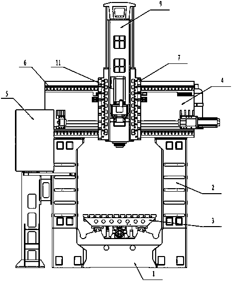
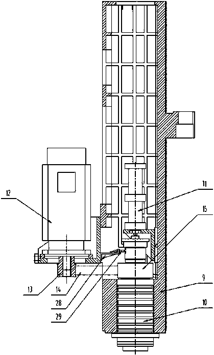
[0047] Embodiment 1: The high-rigidity and high-torque gantry machining center of this example, such as figure 1 , figure 2 , including the bed 1, the bed is provided with a column 2, a workbench 3, a beam 4 is provided at the upper end of the column, a tool magazine 5 is provided at one end of the beam, a beam guide rail 6 is provided on the beam guide rail, and a saddle 7 is slidably connected to the beam guide rail , the saddle is provided with a ram 9 with a high-rigidity guide rail structure, the ram is provided with a main shaft 10 and a knife cylinder 11, the main shaft is connected to the main motor 12 through a pulley reduction device, and a main shaft positioning device is also provided on the main shaft, and the gantry processing The center is equipped with electrical and numerical control systems. The guide rail of the ram is a linear ball guide rail 8 larger than the guide rail specification of the workbench. Such as image 3 , Figure 4 , the main motor 12 i...

Embodiment 2

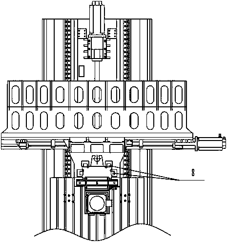
[0049] Embodiment 2: The high-rigidity and high-torque gantry machining center of this example, such as Figure 5 , Figure 6 , including the bed 1, the bed is provided with a column 2, a workbench 3, a beam 4 is provided at the upper end of the column, a tool magazine 5 is provided at one end of the beam, a beam guide rail 6 is provided on the beam guide rail, and a saddle 7 is slidably connected to the beam guide rail , the saddle is provided with a ram 9 with a high-rigidity guide rail structure, the ram is provided with a main shaft 10 and a knife cylinder 11, the main shaft is connected to the main motor 12 through a pulley reduction device, and a main shaft positioning device is also provided on the main shaft, and the gantry processing The center is equipped with electrical and numerical control systems. The guide rail of the ram is a larger ram wide guide rail 19 than the workbench guide rail width. Such as Figure 7 , the main motor 12 is connected to the first syn...

Embodiment 3

[0051] Embodiment 3: The high-rigidity and high-torque gantry machining center of this example, such as Figure 8 , the spindle positioning device includes a spindle encoder 30 fixed on the spindle 10 .

[0052] All the other are with embodiment 2.


PUM


Abstract

The invention relates to a machining center, and in particular to a gantry machining center with high rigidity and large torque. The gantry machining center mainly solves the technical problems existing in the prior art that a high-low gear reduction gearbox is expensive, a high speed gear works in the limiting condition, the failure rate is high, and the cost of using and maintenance is high; requirements of processing at the reduction ratio of 1:2/1:3, and the like cannot be satisfied; the rigidity of a main shaft of a vertical processing is bad, tool changing failure frequency is high, and the like. The gantry machining center comprises a lathe bed, wherein the lathe bed is provided with a vertical column and a working table; a cross beam is arranged at the upper end of the vertical column; a tool magazine is arranged at one end of the cross beam; the cross beam is provided with a cross beam guide rail, a sliding saddle is slidably connected with the cross beam; the sliding saddle is provided with a ram of a high rigid guide rail structure; the ram is provided with the main shaft and a tool hitting cylinder; the main shaft is connected with a main motor through a reducing gear with wheels; the main shaft is further provided with a main shaft positioning device; the gantry machining center is provided with an electrical and numerical control system.

Description

technical field [0001] The invention relates to a machining center, in particular to a high-rigidity and large-torque gantry machining center. Background technique [0002] The existing machining center has poor rigidity of the machine tool spindle device; when the spindle speed is lower than the rated speed, the power of the main motor decreases proportionally with the speed drop, resulting in poor cutting efficiency and energy waste. [0003] Existing machining centers are mainly used in the processing of non-ferrous metal parts, ferrous metal parts, and new difficult-to-machine material parts. In order to improve the machining accuracy and cutting efficiency of parts, the existing technology is developing in the direction of high speed and high precision. The spindle speed is generally 8000- 15000rpm, the electric spindle can reach more than 80000rpm; but the cutting torque and effective power are small at low speed, which cannot meet the requirements of rough machining o...

Claims


Application Information

Patent Timeline
Patent Type & Authority Applications(China)
IPC IPC(8): B23Q5/04B23Q5/20
Inventor 王元庆
Owner HANGZHOU DATIAN CNC MACHINE TOOL
Why Eureka
Try Eureka