
Compressed-air energy-storing power generation system adopting unsteady state compression process

A compressed air energy storage and compressed air technology, applied in the direction of engine components, machines/engines, liquid variable capacity machinery, etc., can solve problems such as waste of compression energy, abandoned wind, instability, etc., to increase temperature and improve efficiency , Improve the effect of working ability

Active Publication Date: 2013-10-16
TECHNICAL INST OF PHYSICS & CHEMISTRY - CHINESE ACAD OF SCI
View PDF4 Cites 25 Cited by
  • Summary
  • Abstract
  • Description
  • Claims
  • Application Information

AI Technical Summary

Problems solved by technology

However, the power generation characteristics of this renewable energy are constrained by natural conditions, characterized by intermittent power generation and unstable power generation. Taking wind power as an example, the design value of the average annual utilization hours of wind turbines in my country in 2012 was 2300h, and the actual value was 1900h. In some areas, it is even less than 1500h, resulting in a large amount of abandoned wind power
In the compressed air energy storage power generation system, the volume of the gas storage device is a fixed value, so the process of gas storage is a process of changing pressure, but in the traditional compression process, the design rating of the outlet pressure of the compressor remains unchanged. , the outlet pressure of the compressor is relatively high. For the gas storage device, it is a process of pressure from low to high, and a considerable amount of compression energy is wasted in the middle.

Method used


Image

  • Compressed-air energy-storing power generation system adopting unsteady state compression process

Examples


Embodiment Construction

[0022] The specific implementation manners of the present invention will be further described in detail below in conjunction with the accompanying drawings and embodiments. The following examples are used to illustrate the present invention, but not to limit the scope of the present invention.

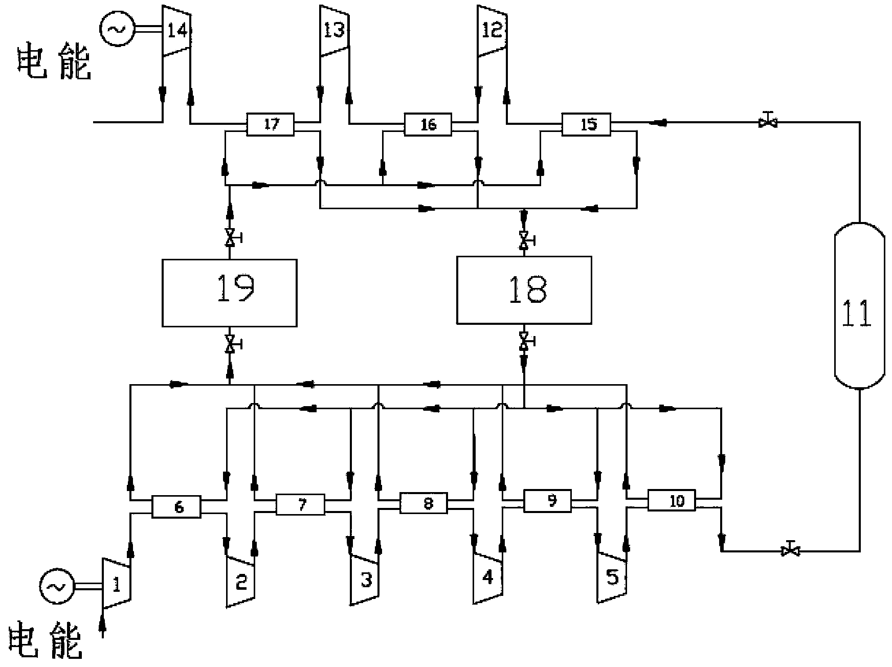
[0023] Such as figure 1 As shown, the present invention is a compressed air energy storage power generation system adopting an unsteady-state compression process, which includes: compressor units 1-5, gas storage device 11 and turbine generator units 12-14, and the compressor units 1-5 The outlet of 5 is connected to the inlet of the gas storage device 11 to provide compressed air for the gas storage device 11; when the compressor units 1 to 5 provide compressed air for the gas storage device 11, the outlet pressure of the compressor units 1 to 5 varies with the The pressure in the gas storage device 11 changes synchronously; the gas storage device 11 stores air compressed by the comp...


PUM


Abstract

The invention discloses a compressed-air energy-storing power generation system adopting an unsteady state compression process. The compressed-air energy-storing power generation system adopting the unsteady state compression process comprises a compressor unit, an air storage device, a turbine generator unit and a heat recovery system, wherein an outlet of the compressor unit is connected with an inlet of the air storage device, and the compressor unit provides compressed air for the air storage device. When the compressor unit provides the compressed air for the air storage device, the pressure of the outlet of the compressor unit synchronously changes along with the pressure in the air storage device, the air storage device stores the compressed air of the compressor unit and provides the compressed air for the turbine generator unit, the heat recovery system feeds back compressed heat to air of the turbine side to improve the temperature of the air, and therefore work of the air can be improved. According to the compressed-air energy-storing power generation system adopting the unsteady state compression process, by means of achievement of synchronous change between the discharge pressure of the outlet of the compressor unit and the air-storing pressure, gradual increase of the power of the compressor unit can be achieved. Due to the unsteady state compression process, under the condition that the compressed air in the same situation is obtained, electric energy consumed by the compressor unit can be reduced, and the transferring efficiency of the electric energy of the system can be improved.

Description

technical field [0001] The invention relates to the field of electric energy storage, in particular to a compressed air energy storage power generation system adopting an unsteady compression process. Background technique [0002] With the continuous growth of my country's power grid capacity, the increasing peak-to-valley difference, and the vigorous development of renewable energy, distributed energy supply and smart grid, there is an increasing demand for large-scale development of the energy storage industry. According to the statistics of the National Power Dispatching and Communication Center, the amplitude of the "peak-valley difference" of my country's power grid load is increasing year by year. The introduction of energy storage systems into the power grid is an urgent need to achieve peak shaving of the power grid. At present, due to the existence of peak power supply shortages, some power grids have to adopt measures of mandatory power cuts, which not only hinder...

Claims


Application Information

Patent Timeline
IPC IPC(8): F04B41/02F04B41/06F04B39/06F01D15/10F01D25/10
CPCY02E60/15Y02E60/16
Inventor 王俊杰王思贤薛小代周远
Owner TECHNICAL INST OF PHYSICS & CHEMISTRY - CHINESE ACAD OF SCI
Learn More