Sawing machine

A sawing machine and chainsaw technology, applied in the field of sawing machines, can solve the problems of discontinuous cutting surface of wood, discontinuous movement of chainsaw, inability to cut wood, etc., so as to reduce the use of labor, increase market competitiveness, and improve efficiency.

Active Publication Date: 2013-10-23
颜夏根
View PDF13 Cites 5 Cited by
  • Summary
  • Abstract
  • Description
  • Claims
  • Application Information

AI Technical Summary

Problems solved by technology

The chainsaws in the above two patents are all moved on the guide rail by the motor, and a large vibration will be generated between the saw blade and the wood during cutting. Jumping occurs, causing the chainsaw to move discontinuously, making the cut surface of the wood discontinuous, reducing the quality of the wood, and generating a lot of noise; and the above two patents can only drive the chainsaw to move through the motor, and cannot when the motor is damaged. Cutting wood, cannot be moved by manually pushing the chainsaw, there are limitations

Method used


Image

  • Sawing machine
  • Sawing machine
  • Sawing machine

Examples


Embodiment 1

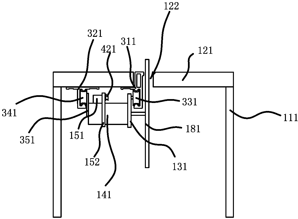
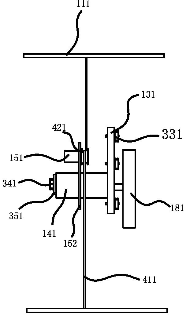
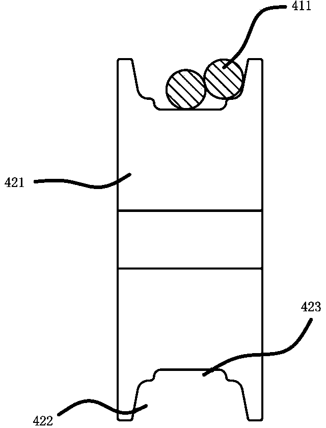
[0045] A sawing machine, the sawing machine includes a frame 111, a workbench 121 fixed on the frame 111 and an electric saw that can slide along the workbench 121, and the electric saw includes a handle for manually pushing the electric saw to move, such as figure 1 and figure 2 As shown, the saw machine also includes a guide rope 411 and a fixed rod 431. The guide rope 411 is arranged along the sliding direction of the chainsaw. The guide rope 411 includes a steel wire rope 412 and a rubber sheath 413 wrapping the steel wire rope 412. One end of the guide rope 411 is fixed on the frame 111 On one side, the other end of guide rope 411 is fixed on the fixed rod 431, and fixed rod 431 is positioned at the other side of frame 111, is provided with between fixed rod 431 and frame 111 and can adjust the fixed rod 431 and frame 111 one side. The distance between them makes the guide rope 411 tense or loosen the adjustment mechanism. A walking motor 151 that can drive the chainsaw ...

Embodiment 2

[0062] The structure and principle of this embodiment are basically the same as that of Embodiment 1. The difference is that the adjustment mechanism includes an adjustment hole and a nut provided on the frame. The rod passes through the nut and is threadedly connected with the nut, the end of the fixed rod positioned inside the frame is fixed with the guide rope, and the end of the fixed rod positioned outside the frame is the handle end. By turning the fixed rod at the handle end, the guide rope can be tensioned when the fixed rod moves out of the frame to a certain position. At this time, the walking motor is used to control the walking of the chainsaw. The rope is slack, and the movement of the chainsaw is manually controlled at this time.

Embodiment 3

[0064] The structure and principle of this embodiment are basically the same as that of Embodiment 1, the difference is that: Figure 19 and Figure 20 As shown, the handle is a wireless handle, and the wireless handle includes a handle 521 and a connecting plate 511, a wireless transmitter 533 is fixed on the handle 521, a wireless receiver is fixed on the mounting plate 131, the wireless receiver is connected to the controller, and the handle One end of 521 is fixed on the connection plate 511 , and the other end of the connection plate 511 is fixed with a protective cover 561 , and the protective cover 561 is located above the saw blade 181 . When the sawing machine is switched to manual mode, the handle 521 is used to push the chainsaw to move to realize manual cutting of wood; the wireless receiver is connected to the driving motor 141, and the wireless transmitter 533 on the handle 521 transmits a signal, so that the wireless receiver controls the driving motor 141 The ...


PUM


Abstract

The invention provides a sawing machine, and belongs to the technical field of wood-working machines. The sawing machine solves the technical problems that an existing sawing machine can only drive an electric saw to move through a motor, and the electric saw cannot be manually pushed to move. The sawing machine comprises a rack, a workbench fixedly arranged on the rack and an electric saw capable of sliding along the workbench, the electric saw is provided with a handle used for manually pushing the electric saw to move, the sawing machine further comprises a guide rope and a fixed rod, the guide rope is arranged in the sliding direction of the electric saw, one end of the guide rope is fixedly arranged at one end of the rack, the other end of the guide rope is fixedly arranged on the fixed rod, the fixed rod is arranged at the other end of the rack, an adjusting mechanism capable of adjusting the distance between the fixed rod and one end of the rack to tighten or loosen the guide rope is arranged between the fixed rod and the rack, and a walking motor which can drive the electric saw to move along the guide rope when the guide rope is tightened is arranged on the guide rope. The electric saw can be automatically driven to move through the walking motor or is manually pushed to move through the handle, and the sawing machine has the advantage of having multiple operating modes.

Description

technical field [0001] The invention belongs to the technical field of woodworking machinery and relates to a sawing machine. Background technique [0002] Woodworking sawing machine is a small sawing machine. At present, the common saw blade is fixed on a certain position on the sawing machine. For example, a woodworking table saw [CN200954639Y] disclosed in Chinese patent literature includes a frame, a power mechanism, and a circular saw blade. Combined with the saw blade adjustment, the power mechanism includes a series motor and a gear box, the circular saw blade is connected to the output shaft of the gear box and partially exposed through the saw blade groove on the workbench, the saw blade adjustment mechanism combination includes a height adjustment mechanism, The angle adjustment mechanism is composed of a movable plate that can move up and down, a swing plate that drives the movable plate to move, and a screw pair that drives the swing plate to swing. The reduction...

Claims


Application Information

Patent Timeline
Patent Type & Authority Applications(China)
IPC IPC(8): B27B5/18B27B5/29
Inventor 颜夏根
Owner 颜夏根
Why Eureka
Try Eureka