Organic material deposition system

A technology of organic materials and deposition systems, applied in metal material coating process, ion implantation plating, coating, etc., can solve problems such as time increase

Inactive Publication Date: 2013-10-23
SNU PRECISION CO LTD
View PDF2 Cites 0 Cited by
  • Summary
  • Abstract
  • Description
  • Claims
  • Application Information

AI Technical Summary

Problems solved by technology

[0018] As described above, the manipulator 11 must repeatedly move horizontally to the left and right to transfer the two substrates into the process chamber 20, resulting in the problem of increased tack time for the entire process and unnecessarily increased The size of the large transfer chamber ensures the space for the manipulator 11 to reciprocate horizontally

Method used


Image

  • Organic material deposition system
  • Organic material deposition system
  • Organic material deposition system

Examples


Embodiment Construction

[0032] Hereinafter, exemplary embodiments of an organic material deposition system according to the present invention will be described in detail with reference to the accompanying drawings.

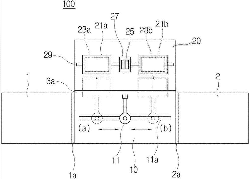
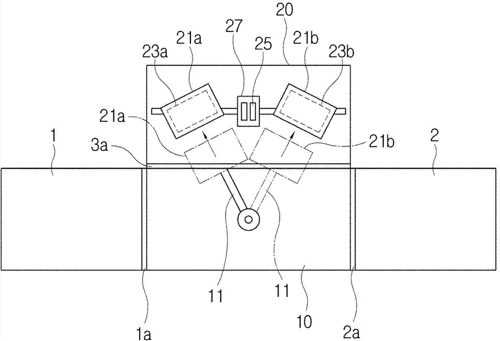
[0033] image 3 is a plan view of an organic material deposition system according to an embodiment of the present invention. Such as image 3 As shown, the organic material deposition system according to the embodiment of the present invention includes a process chamber 20 and a transport chamber 10, in which the process of depositing an organic material on a substrate is implemented in the process chamber 20, and in the transport chamber 10, the substrate is transported to process chamber 20. Of course, the transfer chamber 10 may be connected to a load / unload chamber or a load lock chamber as described in conventional organic material deposition systems.

[0034] As described in conventional organic material deposition systems, the process chamber 20 is provided with substrate holde...


PUM


Abstract

The invention relates to an organic material deposition system, particular to an organic material deposition system which is used for conveying base materials to a processing chamber by driving a mechanical arm in a conveying chamber and which is simplified in structure and thereby being shortest in reversing time for an organic material deposition process for the base materials when the organic material deposition process is performed on the two base materials in the processing chamber.

Description

technical field [0001] The present invention relates to an organic material deposition system, and more particularly to a structural simplification for driving a manipulator in a transfer chamber to transfer substrates into a process chamber, so that when organic materials are applied to two substrates in the process chamber During the deposition process, the organic material deposition system used for the shortest switching time of the organic material deposition process of the substrate. Background technique [0002] Organic electroluminescent display device (organic electroluminescent display device) is a self-emissive display device that has attracted attention due to its advantages of wide viewing angle, good contrast ratio and fast response time. [0003] As is generally known, an organic electroluminescent device provided in an organic electroluminescent display device is configured to include a first electrode and a second electrode (for example, a positive electrode...

Claims


Application Information

Patent Timeline
IPC IPC(8): C23C14/24C23C14/12H05B33/10H01L51/56
CPCH01L21/67742C23C14/042C23C14/24C23C14/568
Inventor 李亨培安东愿
Owner SNU PRECISION CO LTD
Why Eureka
Try Eureka