Composite-structure porous shaft slip form construction device and method

A complex structure, sliding form technology, applied in vertical shaft equipment, wellbore lining, earthwork drilling, etc., can solve the problems of high construction cost, complex procedures, long construction period, etc., save materials, avoid repeated disassembly and assembly, and improve work efficiency Effect

Inactive Publication Date: 2013-10-23
SINOHYDRO BUREAU 14 CO LTD
View PDF4 Cites 13 Cited by
  • Summary
  • Abstract
  • Description
  • Claims
  • Application Information

AI Technical Summary

Problems solved by technology

[0003] 1. The purpose of the invention: to overcome the disadvantages of complex procedures, high cons

Method used


Image

  • Composite-structure porous shaft slip form construction device and method
  • Composite-structure porous shaft slip form construction device and method
  • Composite-structure porous shaft slip form construction device and method

Examples


Embodiment Construction

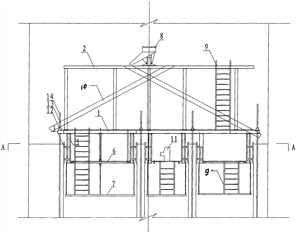
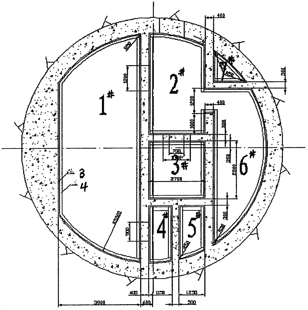
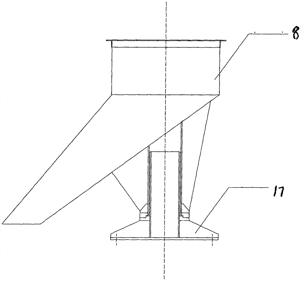
[0007]According to the actual situation of the multi-hole shaft with complex structure, the slip-form construction device for the multi-hole shaft with complex structure is designed and manufactured. The construction device consists of a sliding form system, a material distribution system, and a hydraulic system; the sliding form system consists of a formwork group (3), an enclosure (4), a lifting frame (5), a main platform (1), an auxiliary platform (6), stairs ( 9), climbing rods (14); the material distribution system is composed of a distribution platform (2), a rotating hopper (8), a fixed chute (10), and a plastering platform (7); the hydraulic system is composed of a hydraulic jack (12), a hydraulic pump Station (11), limit leveler (13); Its characteristics are: 1. Formwork group composition and size: the formwork is composed of panels and webs, and is made of steel plates with the grade Q235, and the panels are the parts that are in contact with concrete. During the pou...


PUM

PropertyMeasurementUnit
Diameteraaaaaaaaaa
Diameteraaaaaaaaaa
Radiusaaaaaaaaaa

Abstract

Disclosed is a composite-structure porous shaft slip form construction device and method. The construction device comprises a form set, an enclosure, a lifting rack, a main platform, auxiliary platforms, stairs, booms, distribution platforms, a rotary hopper, fixed chutes, plastering platforms, hydraulic jacks, hydraulic pump stations, and limit levelers. Twenty-five types of 96 rectangular and long-arc steel form slabs with welded webs are connected through bolts to form the form set. The enclosure is connected with a form through bolts and is connected with the lifting rack which is connected with the main platform. The jacks are fixed on the main platform. The booms ascend to drive the whole slip form to ascend. The rotary hopper is connected with the fixed chute and feeds material in different directions. The construction method includes pouring concrete while the slip form ascends to form at one time; testing and correcting vertical and horizontal positions of the form, the booms and the platforms during slip-ascending. The construction device and method has the advantages that procedures are less, the efficiency is increased by 1.5 times, the material and manpower are saved, and the cost is reduced.

Description

1. Technical field [0001] The invention belongs to the technical field of hydropower civil engineering, and in particular relates to a device and a method for large-scale hydropower engineering construction. 2. Background technology [0002] Concrete pouring for underground power stations of large-scale hydropower projects requires a lot of work and high quality requirements. The excavation shaft of the No. 4 outgoing line of the Xiluodu Right Bank Underground Power Station has a diameter of 12.5m, and the height of the lower section is 217.95m, and the thickness is 35cm; There are 7 parts of the air supply shaft and the cable shaft. There are a large number of reserved holes between each part, and the structure is complex, which brings difficulties to the concrete pouring work. At present, the relatively complex shaft concrete construction of domestic large-scale hydropower civil engineering underground projects usually adopts the conventional construction method of layere...

Claims


Application Information

Patent Timeline
IPC IPC(8): E02B9/00E21D5/12E21D5/04
CPCY02E10/22Y02E10/20
Inventor 黄岗曾理偰光恒史志峰陈翕和陈芝焕王继孝张发斌张保平冯宏亮鹿永久郭学红梁志昆陆永昆张玉彬杨立峰邓孝洪高兴月李毅熊训邦
Owner SINOHYDRO BUREAU 14 CO LTD
Why Eureka
Try Eureka