Optoisolator with bandwidth of 1 mu m

An optical isolator and bandwidth technology, applied in optics, instruments, nonlinear optics, etc., can solve the problems of unstable characteristics and damage to the LD light source unit, and achieve polarization independence, miniaturization, and improvement of magnetic flux density. Effect

Inactive Publication Date: 2013-10-23
SHIN ETSU CHEM IND CO LTD
View PDF10 Cites 2 Cited by
  • Summary
  • Abstract
  • Description
  • Claims
  • Application Information

AI Technical Summary

Problems solved by technology

[0004] However, although fiber lasers have the characteristics of high conversion efficiency due to their narrow emission spectrum, on the other hand, they are very

Method used


Image

  • Optoisolator with bandwidth of 1 mu m
  • Optoisolator with bandwidth of 1 mu m
  • Optoisolator with bandwidth of 1 mu m

Examples


Embodiment 1

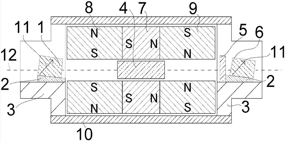
[0197] produced as figure 1 A 1μm bandwidth optical isolator constructed as shown.

[0198] The incident polarizer 1 and the outgoing polarizer 6 use rutile single crystal, and the light transmission surface thereof is processed into a parallel plate with a thickness of 1.0 cm, and the optical axis 11 is inclined 47.8 degrees relative to the optical axis 12 . figure 1 The direction of inclination depicted in is toward the inside of the paper. In addition, an anti-reflection film with a center wavelength of 1.06 μm was applied to the light transmission surface of the flat-plate polarizer. At the same time, in order to prevent the reflected light from the light transmission surface from returning to the incident light path, the bottom surface of the polarizer was adhered. It is fixed on the wedge glass 2 with an inclination angle of only 5 degrees, and loaded on the polarizer bracket 3.

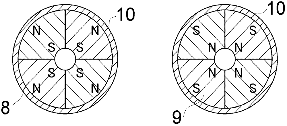
[0199] And, let the Faraday rotator 4 be located at the central position of the hollow po...

Embodiment 2 and 3

[0205]In the above formula (I), the correspondence relationship between the Tb content x (0.5 to 1.0) and the Verdet constant was examined. As Example 2, (Tb 0.5 Y 0.5 ) 2 o 3 The same procedure as in Example 1 was carried out except for the single crystal of the oxide.

[0206] Furthermore, as Example 3, Tb containing the same weight % and x=1.0 was used 2 o 3 Except for the single crystal of the oxide, it was carried out in exactly the same manner as in Example 1.

[0207] The Verdet constant of a single crystal having the above composition was measured. It can be seen from the results that its Verdet constant is: when x=0.5, 0.27min / (Oe*cm); when x=1.0, 0.43min / (Oe*cm). In addition, in Examples 2 and 3, the extinction ratios were both 35 dB.

[0208] When changing the sample length (optical path length) of the single crystals used in Examples 1 to 3 at intervals of 0.1 cm within the range of 0.7 to 1.1 cm, the magnetic flux density T when the Faraday rotation angle ...


PUM

PropertyMeasurementUnit
Field constantaaaaaaaaaa
Thicknessaaaaaaaaaa
Insertion lossaaaaaaaaaa

Abstract

The invention provides a miniaturized optoisolator with bandwidth of 1 mu m. The miniaturized optoisolator with the bandwidth of 1 mu m is suitable for serving as an optoisolator in high-power lasers used for laser processing and the like, such as a fiber laser. The miniaturized optoisolator with the bandwidth of 1 mu m comprises a Faraday rotor, a first hollow magnet, a second hollow magnet unit and a third hollow magnet unit, wherein the Verdet constant of the Faraday rotor under the wavelength of 1.06 mu m is over 0.27min/(Oe*cm); the first hollow magnet is arranged on the periphery of the Faraday rotor; and the second hollow magnet unit and the third hollow magnet unit are arranged on an optical axis to clamp the first hollow magnet in the middle. The miniaturized optoisolator with the bandwidth of 1 mu m is characterized in that the second hollow magnet unit and the third hollow magnet unit are formed by more than two magnets formed by equal cutting along the direction which forms a 90-degree angle with the optical axis direction, the magnetic flux density B(Oe) applied to the Faraday rotor is within the range of a formula (1) which is that 0.5*104<=B<=1.5*104; and the optical path length L (cm) of the Faraday rotor is within the range of a formula (2) which is that 0.7<=L<=1.10.

Description

technical field [0001] The present invention relates to optical isolators for use in wavelength bandwidths of about 1 μm. This type of optical isolator is widely used in the field of industrial lasers for processing and marking purposes, and is widely used together with high-power lasers. Background technique [0002] Previously, CO2 lasers (10.6 μm) or lamp-pumped YAG lasers (1 μm) have been used in industrial laser processing machines for cutting, welding, marking, etc. [0003] In recent years, the requirements for its processing performance have become more and more stringent, requiring laser processing machines to have higher precision, greater output power and longer life. Under this market requirement, people pay attention to fiber lasers. The characteristic of the fiber laser is that its optical path is entirely composed of optical fibers, through which the optical fiber doped with rare earth elements such as ytterbium (Yb) amplifies the light with a bandwidth of 1...

Claims


Application Information

Patent Timeline
IPC IPC(8): G02F1/09
CPCG02F1/093H01F7/0273
Inventor 矢作晃田边敏之渡边聪明
Owner SHIN ETSU CHEM IND CO LTD
Why Eureka
Try Eureka