Method for workpiece platform micro moving part mechanical parameter estimation

A technology of mechanical parameters and workpiece table, applied in calculation, electrical digital data processing, aerodynamic improvement, etc., can solve the problem of difficult position of the center of mass of the micro-moving part of the workpiece table

Active Publication Date: 2013-10-23
HARBIN INST OF TECH
View PDF2 Cites 4 Cited by
  • Summary
  • Abstract
  • Description
  • Claims
  • Application Information

AI Technical Summary

Problems solved by technology

[0004] The present invention aims to solve the problem that the installation angles of the voice coil motors in the three horizontal directions of the micro-moving part of the workpiece table of the lithography machine and the centroid position of the micro-moving part of the workpiece table are difficult to be accurately measured by traditional precision instruments, and a micro-movement of the workpiece table is provided. Method for Estimating Mechanical Parameters of Moving Parts

Method used


Image

  • Method for workpiece platform micro moving part mechanical parameter estimation
  • Method for workpiece platform micro moving part mechanical parameter estimation
  • Method for workpiece platform micro moving part mechanical parameter estimation

Examples


specific Embodiment approach 1

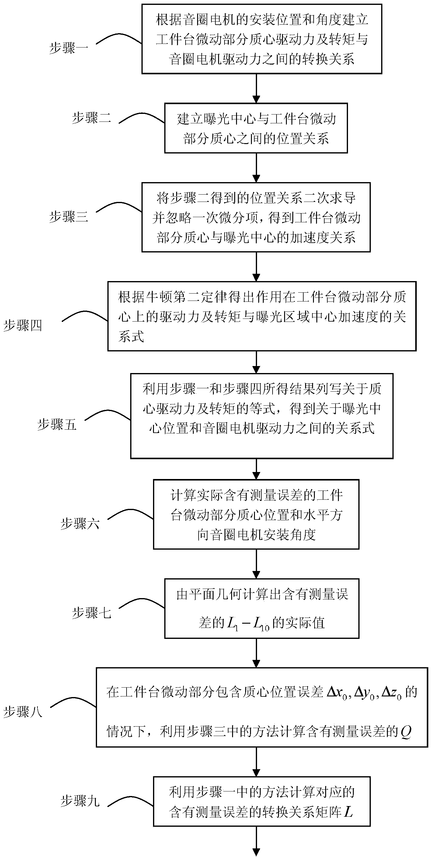
[0037] Embodiment 1: A method for estimating the mechanical parameters of the micro-movement part of the workpiece table in this embodiment is implemented in the following steps:

[0038] 1. According to the installation position and angle of the voice coil motor, establish the conversion relationship between the center-of-mass driving force and torque of the micro-movement part of the workpiece table and the driving force of the voice coil motor;

[0039] 2. Establish the positional relationship between the exposure center and the center of mass of the micro-movement part of the workpiece table;

[0040] 3. Secondary derivation of the positional relationship obtained in step 2 and ignoring the primary differential item to obtain the acceleration relationship between the center of mass of the micro-moving part of the workpiece table and the exposure center;

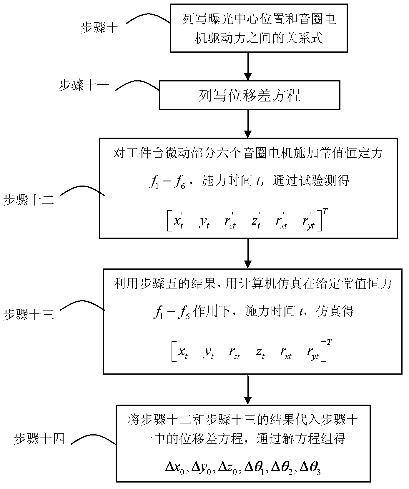
[0041] 4. According to Newton's second law, the relationship between the driving force and torque acting on the center ...

specific Embodiment approach 2

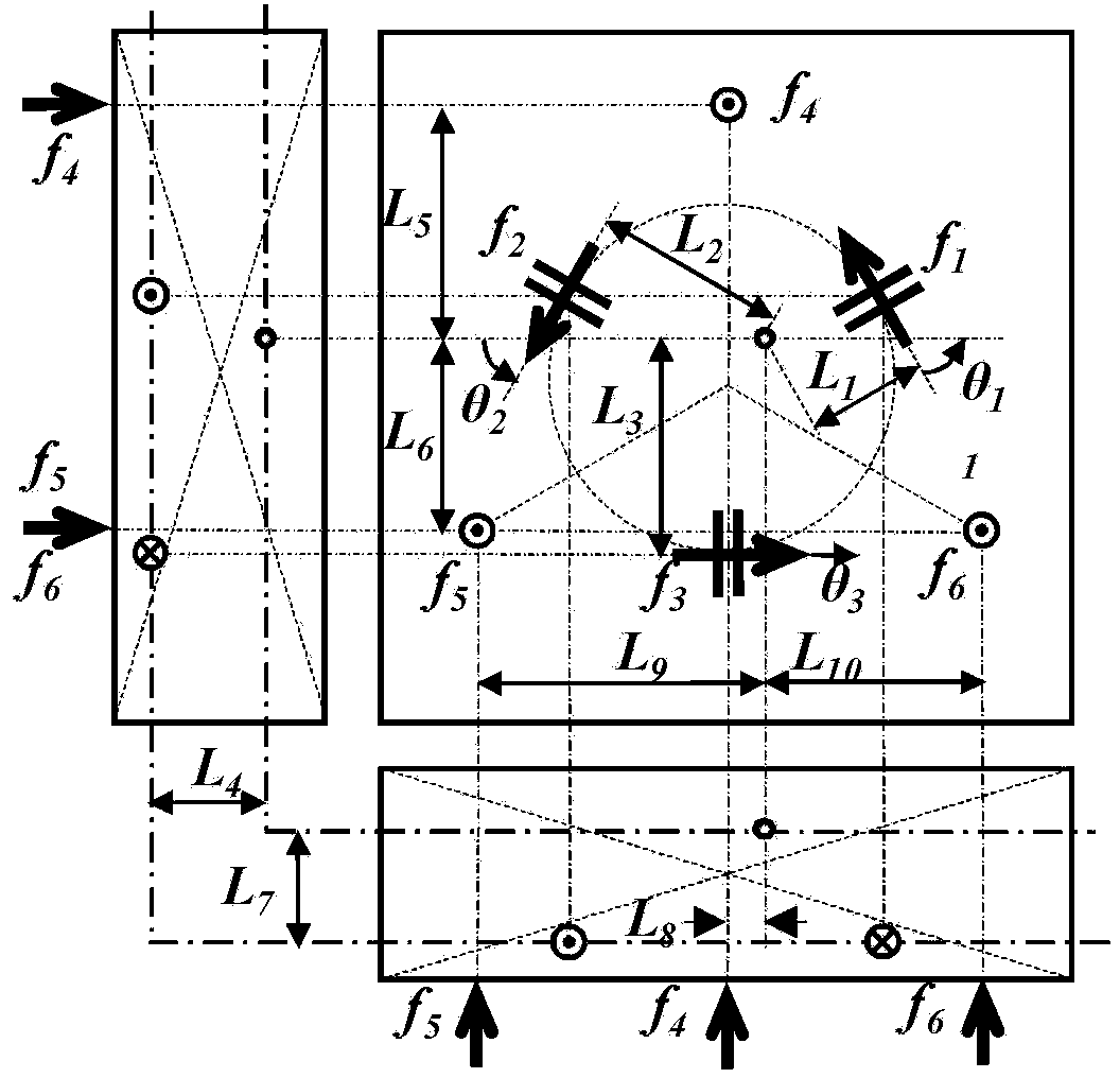
[0066]Specific embodiment 2: The difference between this embodiment and specific embodiment 1 is that in step 1, the conversion relationship between the driving force and torque of the center of mass of the micro-movement part of the workpiece table and the driving force of the voice coil motor is specifically: F cog =L·f

[0067] where the matrix F cog =[F xcog f ycog T zcog f zcog T xcog T ycog ] T ,

[0068] f=[f 1 f 2 f 3 f 4 f 5 f 6 ] T ,

[0069] L = - cos θ 1 - cos θ 2 cos θ 3 0 0 ...

specific Embodiment approach 3

[0071] Embodiment 3: The difference between this embodiment and Embodiment 1 or 2 is that in Step 2, the positional relationship between the exposure center and the center of mass of the micro-movement part of the workpiece table is specifically:

[0072] x cog = x - ( y + y 0 ) r z + ( z + z 0 ) r y y cog ...


PUM


Abstract

The invention mainly relates to a method for workpiece platform micro moving part mechanical parameter estimation, and aims to solve the problem that the installation angle and the centroid position of three horizontal voice coil motors of a photoetching machine workpiece platform micro moving part are hard to accurately measure through a traditional precision instrument. The method comprises the following steps: 1. establishing a transformational relation; 2. establishing a positional relation; 3. carrying out a quadratic derivation on the position relation; 4.obtaining a relational expression of the relative driving force and the torque with the exposure area center acceleration; 5. obtaining a relational expression of the exposure center position and the voice coil motor driving force; 6. setting the actual centroid position and installation angle; 7. obtaining an actual value of L1 to L10 through a plane geometry relation; 8. calculating the actual Q by utilizing the method in step 3; 9. calculating the actual L by utilizing the method in step 1; 10. establishing an error model; 11.listing a displacement difference equation; 12. measuring to obtain [ x't, y't, r'zt, z't, r'xt,r'yt] <T> through an experiment; 13. emulating to obtain [ xt, yt, rzt, zt, rxt,ryt] <T>; 14. solving the equation set to obtain delta x0, delta y0, delta z0, delta theta 1, delta theta 2 and delta theta 3. The invention belongs to the field of super-precision manufacturing.

Description

technical field [0001] The invention belongs to the field of ultra-precision manufacturing, and mainly relates to a method for estimating the mechanical parameters of the micro-movement part of the workpiece table of the lithography machine. Background technique [0002] Lithography machine is the key equipment for manufacturing large-scale integrated circuits, mainly used in the development and production of integrated circuits, semiconductor components, optoelectronic devices, and optical devices. The workpiece table system is a key component of the lithography machine, which mainly realizes the multi-degree-of-freedom movement function of the lithography machine. The precision and speed of its movement directly affect the resolution and production efficiency of the lithography machine. The nanoscale ultra-high precision dynamic tracking and positioning of the workpiece table is the key technology for the development of lithography machines. Since long-stroke linear moto...

Claims


Application Information

Patent Timeline
Patent Type & Authority Applications(China)
IPC IPC(8): G06F17/50
CPCY02T10/82
Inventor 陈兴林王一光李晓杰
Owner HARBIN INST OF TECH
Why Eureka
Try Eureka