Exposure apparatus for optical disc

a technology of optical discs and apparatuses, applied in the direction of digital signal error detection/correction, instruments, recording signal processing, etc., can solve the problems of not being able to calculate the correct difference in the propagating direction, the rotation mechanism generates rotational vibration, and the non-synchronized vibration can be immediately detected during the exposure process, etc., to achieve the effect of reducing enhancing exposure quality, and suppressing the propagating component of rotational vibration

Inactive Publication Date: 2006-06-06
RICOH KK
View PDF8 Cites 2 Cited by
  • Summary
  • Abstract
  • Description
  • Claims
  • Application Information

AI Technical Summary

Benefits of technology

[0019]Therefore, it is an objective of the invention to provide an exposure apparatus for an optical disc. A laser beam emitted from a laser source passes through an exposure system and a condensing device, and then irradiates on the optical disc put on a rotation mechanism fixed on a base. When a pre-determined information is recorded on the optical disc, a base transporting force measuring device is used for measuring a transporting force in the propagating direction to the base that is involved a rotation of the rotation mechanism. By a controller, according to a result of the base transporting force measuring device, it controls the vibrator to vibrate, thereby the transporting force in the propagating direction acted on the base is cancelled. Therefore, it can suppress the propagating component of the rotational vibration when the optical disc is eccentrically chucked on the rotation mechanism. Thus, the propagation accuracy is increased and the exposure quality is enhanced.
[0020]It is another objective of the invention to provide an exposure apparatus for an optical disc. A laser beam emitted from a laser source passes through an exposure system and a condensing device, and then irradiates on the optical disc put on a rotation mechanism fixed on a base. When a pre-determined information is recorded on the optical disc, a linear encoder transporting force measuring device is used for measuring a transporting force in the propagating direction to the optical linear encoder that is involved a rotation of the rotation mechanism, wherein the optical linear encoder is used for detecting a propagation of the slider that is used for mounting the condensing device and moveably installed on the base. By a controller, according to a result of the linear encoder transporting force measuring device, it controls the vibrator to vibrate, thereby the transporting force in the propagating direction acted on the linear encoder is cancelled. Therefore, it can suppress the propagating component of the rotational vibration when the optical disc is eccentrically chucked on the rotation mechanism. Thus, the propagation accuracy is increased and the exposure quality is enhanced.
[0021]It is another objective of the invention to provide an exposure apparatus for an optical disc. A laser beam emitted from a laser source passes through an exposure system and a condensing device, and then irradiates on the optical disc put on a rotation mechanism fixed on a base. When a pre-determined information is recorded on the optical disc, a base transporting force measuring device is used for measuring a transporting force in the propagating direction to the base that is involved a rotation of the rotation mechanism, and furthermore, a linear encoder transporting force measuring device is used for measuring a transporting force in the propagating direction to the optical linear encoder that is involved a rotation of the rotation mechanism, wherein the optical linear encoder is used for detecting a propagation of the slider that is used for mounting the condensing device and moveably installed on the base. By a controller, according to the results of the base transporting force measuring device and the linear encoder transporting force measuring device, it controls the vibrator to vibrate, thereby the transporting forces in the propagating direction acted on the base and the optical linear encoder are cancelled. Therefore, it can suppress the propagating component of the rotational vibration when the optical disc is eccentrically chucked on the rotation mechanism. Besides, the vibrations in the propagating direction due to different propagating paths (relative vibration components having different phases), and the vibrations in the propagating direction from outside can be also suppressed. As a result, the propagation precision is increased and the exposure quality is enhanced.

Problems solved by technology

In the situation, because the exposure apparatus is able to output the non-synchronized vibration irrelevant to each angular position of the rotation of the turntable, and even though in the exposure process the accuracy of the track pitch is exerted serious problem, the non-synchronized vibration can be immediately detected during the exposure process.
However, because the optical disc is usually placed on the turntable with an eccentricity of several ten μm with respect to the outer radius, the rotation mechanism generates rotational vibration due to the centrifugal force during rotation.
Therefore, the irradiation position of the laser beam at side of the turntable varies with the rotation angle, thereby it cannot calculate the correct difference in the propagating direction.
As a result, it cannot perform an accurate correction because the tiny sliding device is moved according to the incorrect measured signal.
In contrast, track pitches are changed and the exposure quality becomes worse.
However, because the pitch accuracy formed on the optical disc is determined by the relative vibration between the turntable and the moving stage, it is worse for the correction accuracy to perform the propagating correction by only using the detected result of the slider.
As a result, the exposure quality cannot be increased and enhanced.
However, as same as the method in the Japanese Laid Open 10-261245, it is worse for the correction accuracy to perform the propagating correction by only using the detected result of the slider.
As a result, the exposure quality cannot be increased and enhanced.
In addition, according to the disclosures in the Japanese Laid Open 10-293928, Japanese Laid Open 10-261245, and Japanese Laid Open 8-329476, because the piezoactuator used as the correction mechanism for the propagating direction is installed on the fore-end or frame of the optical head, the structure is complex and its assembly is very difficult.
In addition, the mechanical rigidity is reduced, and the servo gain of the propagating device cannot be set high, which inconvenient control occurs.

Method used


Image

  • Exposure apparatus for optical disc
  • Exposure apparatus for optical disc
  • Exposure apparatus for optical disc

Examples


first embodiment

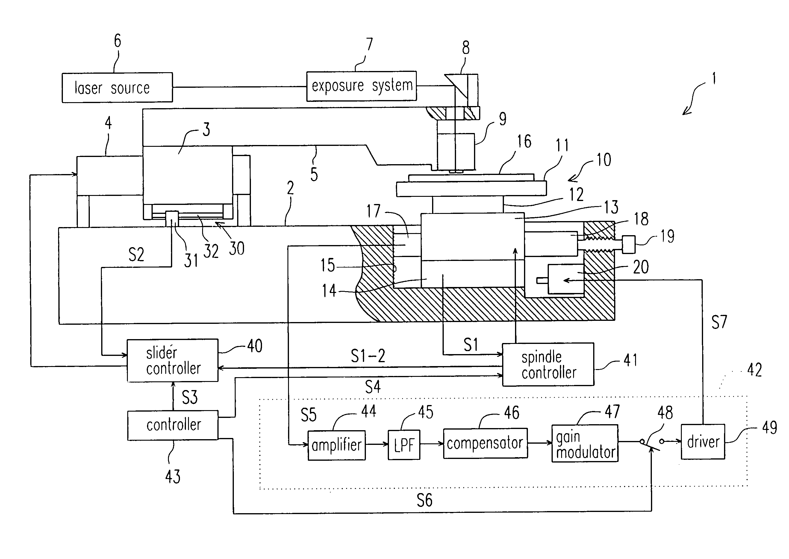
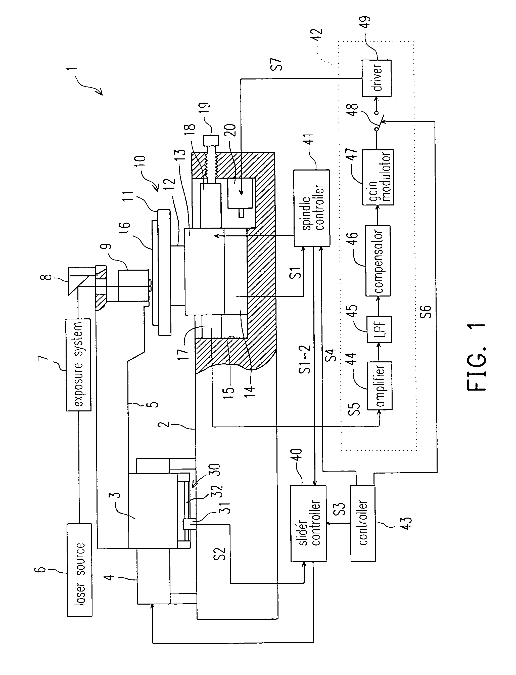
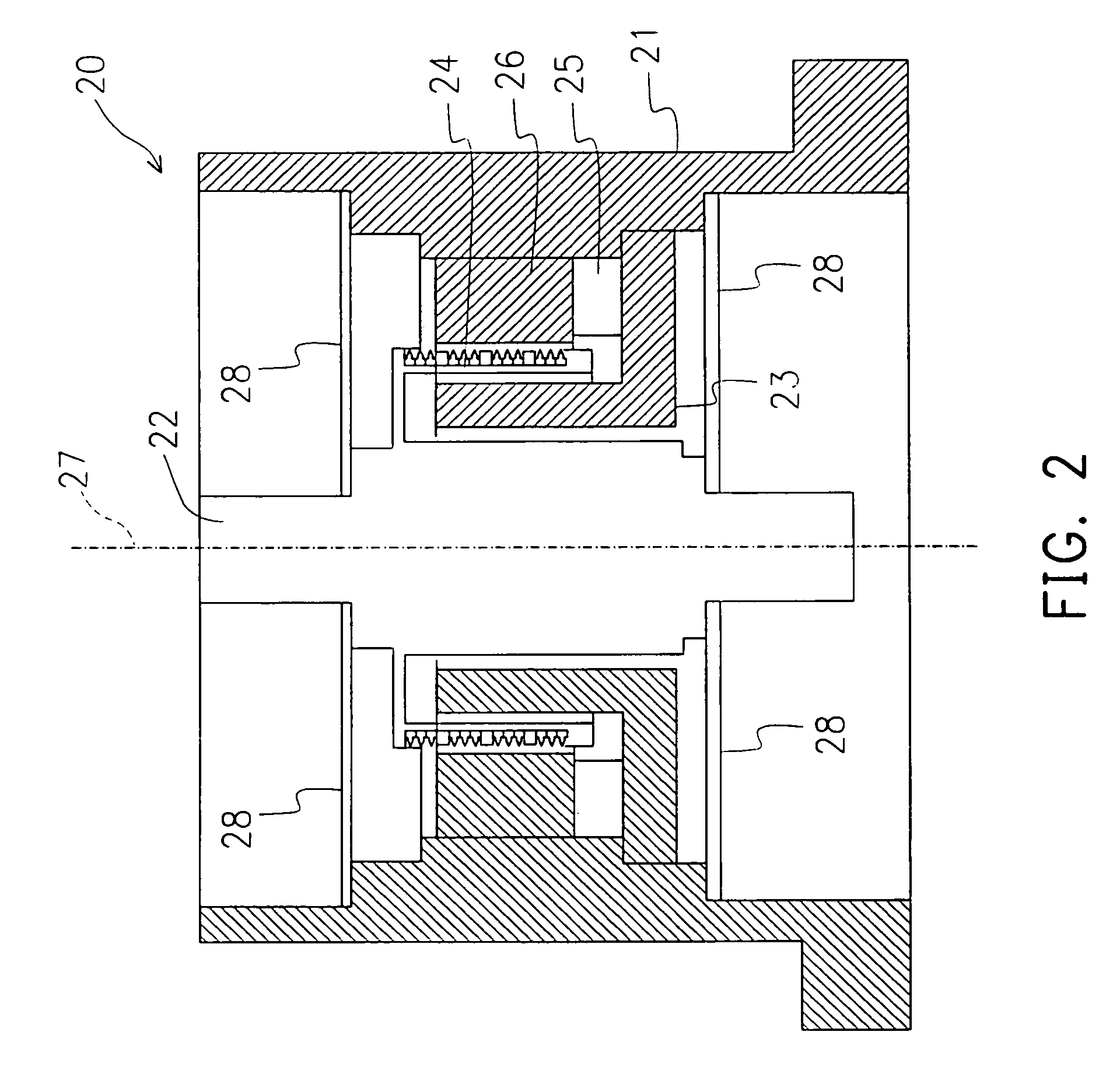
[0061]FIGS. 1 and 2 show an exposure apparatus according to the first embodiment of the invention. FIG. 1 shows a cross-sectional view from one side of the exposure apparatus of the invention, and FIG. 2 shows a cross-sectional view of a vibrator in FIG. 1.

[0062]As shown in FIG. 1, in the exposure apparatus 1, the fixer of a slider 3 is fixed on a base 2 and the base 2 is installed on a vibration eliminating device (not shown), such as a servo mount using air pressure. The slider 3 is floating by a static pressure generated by compressed air supplied externally. One side of a moving plate is fixed on the slider 3, and a laser source 6, an exposure system 7, a folding mirror 8 and a condenser 9 are mounted on the other side of the moving plate 5.

[0063]A rotation mechanism 10 is installed under the condenser 9. The rotation mechanism 10 comprises a turntable 11, a spindle 12 that is floating along a thrust and a radial directions by a static pressure generated by compressed air suppli...

second embodiment

[0083]FIG. 3 shows a cross-sectional view of an exposure apparatus for an optical disc according to the second embodiment of the invention.

[0084]In addition, similar to the exposure apparatus shown in the first embodiment, a measurer is assembled on an installer of an optical linear encoder installed under the slider. In the second embodiment, the components same as the first embodiment are labeled in the same numerals and their corresponding detail descriptions are omitted.

[0085]As shown in FIG. 3, in the exposure apparatus for the optical disc 50, the fixer 4 of a slider 3 is fixed on a base 2 that is installed on a vibration eliminating device (not shown). An optical linear encoder 30 is installed under the slider 3. The optical linear encoder 30 comprises a receiver 31 and a scale 32. By means of the movement of the moving plate 5 formed on the slider 3, the optical linear encoder 30 can measure the propagating position of the condenser 9 installed on the other side of the movin...

third embodiment

[0096]FIG. 4 shows a cross-sectional view of an exposure apparatus for an optical disc according to the third embodiment of the invention.

[0097]In addition, the third embodiment is a combination of the first and the second embodiments. Measurers are installed under the rotation mechanism and the slider. Similarly, in the third embodiment, the components same as the first and the second embodiments are labeled in the same numerals and their corresponding detail descriptions are omitted.

[0098]As shown in FIG. 4, in the exposure apparatus for the optical disc 60, the receiver 31 of the optical linear encoder 30 installed under the slider 3 is fixed on the installer 51. The installer 51 is gripped by an measurer 52 and a fixer 53 that applies a predetermined pressure to the measurer 52. The fixer 53 is fixed to the base 2 through a fixing block 54. The measurer 52 is used for measuring and detecting the vibration transporting force in the propagating direction.

[0099]In addition, similar...


PUM

PropertyMeasurementUnit
outer radiusaaaaaaaaaa
transporting force measuringaaaaaaaaaa
transporting forceaaaaaaaaaa

Abstract

An exposure apparatus for an optical disc used for eliminating the vibrations in the propagating direction when a rotation mechanism rotates. The slider controller 40 and the spindle controller 41 of the exposure apparatus 1 are activated, and the then the optical disc begins to be rotated by an AC synchronized motor. Through a condensing device 9, laser beams emitted form the laser source 6 are irradiated on the optical disc for exposure. At this time, the optical disc is eccentrically chucked on the rotation mechanism, resulting a rotational vibration of the whole rotation mechanism. A measurer 17 is used for detecting a propagating component of the rotational vibration, and a vibrator controller 42 controls the vibrator 20 as the output of the measurer 17 approaches zero. Therefore, the vibration in the propagating direction of the base 2 is cancelled, and the propagation accuracy is increased and the exposure quality is enhanced.

Description

CROSS-REFERENCE TO RELATED APPLICATION[0001]This application is a Rule 1.53(b) continuation, and claims the priority, of U.S. Ser. No. 09 / 902,242, filed Jul. 10, 2001, now U.S. Pat. No. 6,754,153, the entire contents of which is herein incorporated by reference. This application also claims the priority benefit of Japanese application no. 2000-209777, filed on Jul. 11, 2000, and Japanese application no. 2000-275604; filed on Sep. 11, 2000.BACKGROUND OF THE INVENTION[0002]1. Field of the Invention[0003]The present invention is related to an exposure apparatus for an optical disc. More particular, the present invention is related to an exposure apparatus having vibration means capable of vibrating to eliminate vibrations along the propagating direction as a rotation mechanism rotates, thereby pitches between two adjacent tracks on the optical disc can be exposed with a high precision. In addition, the present invention is related to an the exposure apparatus that a three-dimensional s...

Claims


Application Information

Patent Timeline
Patent Type & Authority Patents(United States)
IPC IPC(8): G11B7/00G11B7/095G11B7/26G11B33/08
CPCG11B33/08G11B7/261G11B7/095
Inventor OBARA, TAKASHI
Owner RICOH KK
Why Eureka
Try Eureka