Exposure apparatus for optical disc
a technology of optical discs and apparatuses, applied in the direction of digital signal error detection/correction, instruments, recording signal processing, etc., can solve the problems of not being able to calculate the correct difference in the propagating direction, the rotation mechanism generates rotational vibration, and the non-synchronized vibration can be immediately detected during the exposure process
- Summary
- Abstract
- Description
- Claims
- Application Information
AI Technical Summary
Benefits of technology
Problems solved by technology
Method used
Image
Examples
first embodiment
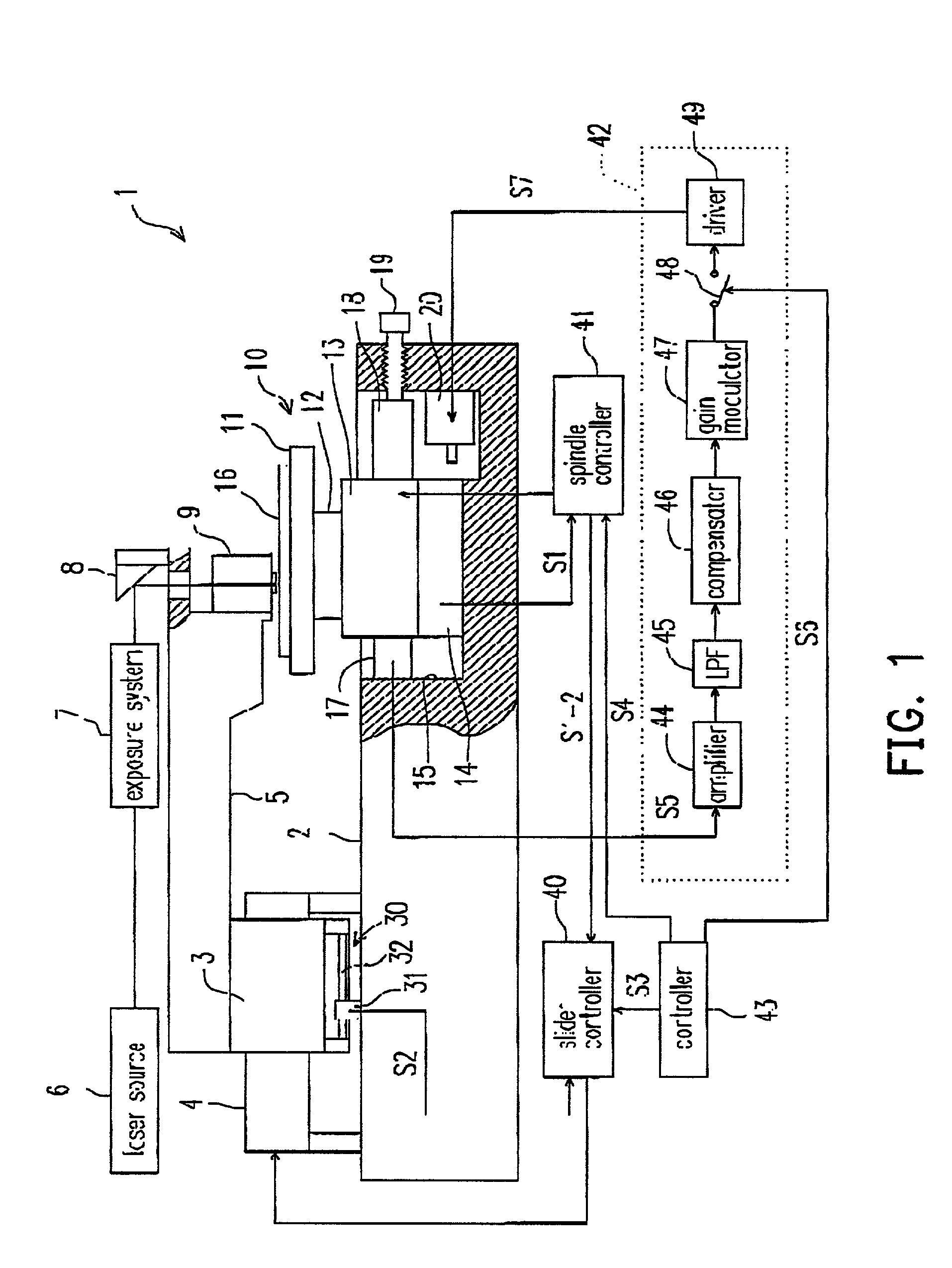
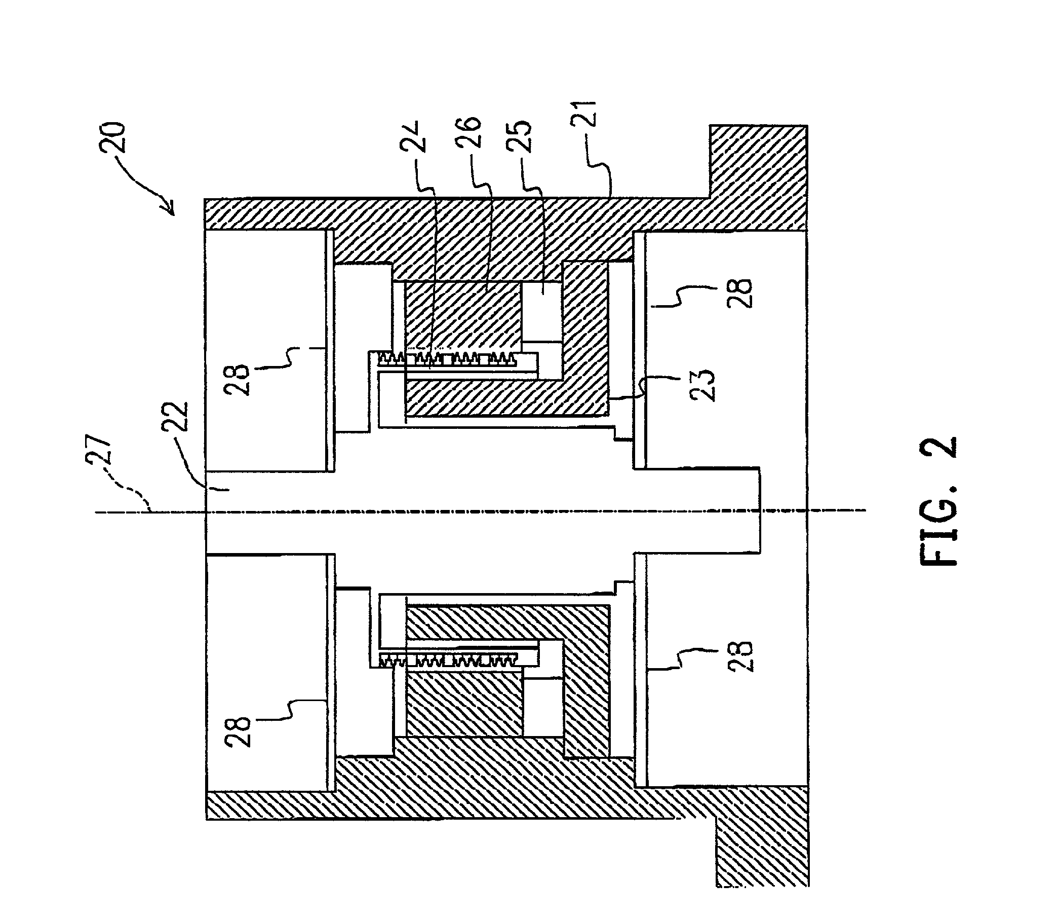
[0059] FIGS. 1 and 2 show an exposure apparatus according to the invention. FIG. 1 shows a cross-sectional view from one side of the exposure apparatus of the invention, and FIG. 2 shows a cross-sectional view of a vibrators in FIG. 1.
[0060] As shown in FIG. 1, in the exposure apparatus 1, the fixer of a slider 3 is fixed on a base 2 and the base 2 is installed on a vibration eliminating device (not shown), such as a servo mount using air pressure. The slider 3 is floating by a static pressure generated by compressed air supplied externally. One side of a moving plate 5 is fixed on the slider 3, and a laser source 6, an exposure system 7, a folding mirror 8 and a condenser 9 are mounted on the side of the moving plate 5.
[0061] A rotation mechanism 10 is installed under the condenser 9. The rotation mechanism 10 comprises a turntable 11, a spindle 12 that is floating along a thrust and a radial directions by a static pressure generated by compressed air supplied externally and capabl...
second embodiment
[0081] FIG. 3 shows a cross-sectional view of an exposure apparatus for an optical disc according to the second embodiment of the invention.
[0082] In addition, similar to the exposure apparatus shown in the first embodiment, a measurer is assembled on an installer of an optical linear encoder installed under the slider. In the second embodiment, the components same as the first embodiment are labeled in the same numerals and their corresponding detail descriptions are omitted.
[0083] As shown in FIG. 3, in the exposure apparatus for the optical disc 50, the fixer 4 of a slider 3 is fixed on a base 2 that is installed on a vibration eliminating device (not shown). An optical linear encoder 30 is installed under the slider 3. The optical linear encoder 30 comprises a receiver 31 and a scale 32. By means of the movement of the moving plate 5 formed on the slider 3, the optical linear encoder 30 can measure the propagating position of the condenser 9 installed on the other side of the mo...
third embodiment
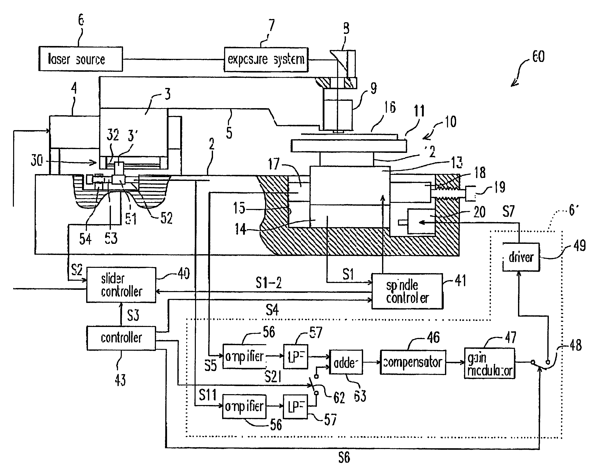
[0094] FIG. 4 shows a cross sectional view of an exposure apparatus for an optical disc according to the third embodiment of the invention.
[0095] In addition, the third embodiment is a combination of the first and the second embodiments. Measurers are installed under the rotation mechanism and the slider. Similarly, in the third embodiment, the components same as the first and the second embodiment are labeled in the same numerals and their corresponding detail descriptions are omitted.
[0096] As shown in FIG. 4, in the exposure apparatus for the optical disc 60, the receiver 31 of the optical linear encoder 30 installed under the slider 3 is fixed on the installer 51. The installer 51 is gripped by an measurer 52 and a fixer 53 that applies a predetermined pressure to the measurer 52. The fixer 53 is fixed to the base 2 through a fixing block 54. The measurer 52 is used for measuring and detecting the vibration transporting force in the propagating direction.
[0097] In addition, simi...
PUM
 Abstract
Description
Claims
Application Information
 - R&D
- Intellectual Property
- Life Sciences
- Materials
- Tech Scout
- Unparalleled Data Quality
- Higher Quality Content
- 60% Fewer Hallucinations
Browse by: Latest US Patents, China's latest patents, Technical Efficacy Thesaurus, Application Domain, Technology Topic, Popular Technical Reports.
© 2025 PatSnap. All rights reserved.Legal|Privacy policy|Modern Slavery Act Transparency Statement|Sitemap|About US| Contact US: help@patsnap.com


