Anti-icing vidicon

A camera and anti-icing technology, which is applied in the field of cameras, can solve the problems of difficult to remove the lens or transparent protective cover, low temperature resistance, easy freezing of the camera, etc., to achieve easy deicing treatment, prevent icing, and reduce the eradication area Effect

Active Publication Date: 2013-10-23
BEIJING GUOWANG FUDA SCI & TECH DEV +1
View PDF5 Cites 11 Cited by
  • Summary
  • Abstract
  • Description
  • Claims
  • Application Information

AI Technical Summary

Problems solved by technology

[0006] The technical problem to be solved in this application is to provide an anti-icing camera to solve the problem that the camera in the power video online monitoring device is easy to freez

Method used


Image

  • Anti-icing vidicon
  • Anti-icing vidicon
  • Anti-icing vidicon

Examples


Embodiment 1

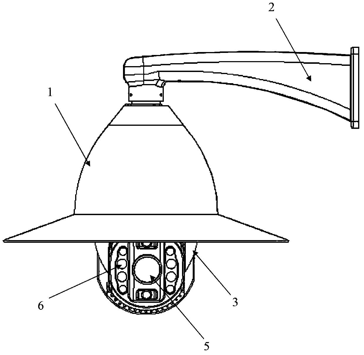
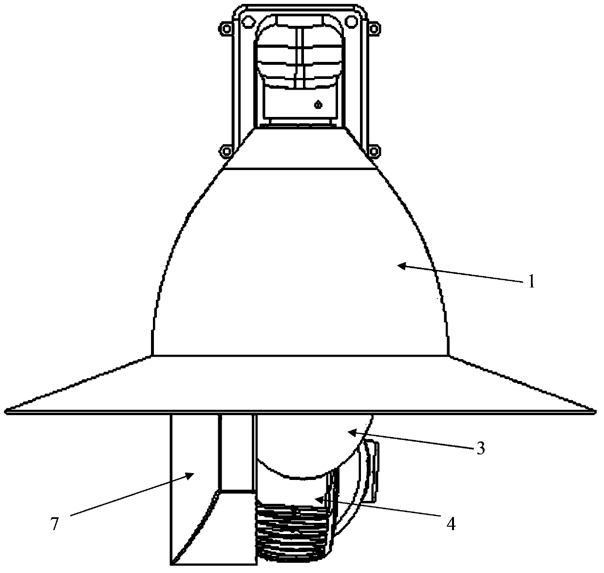
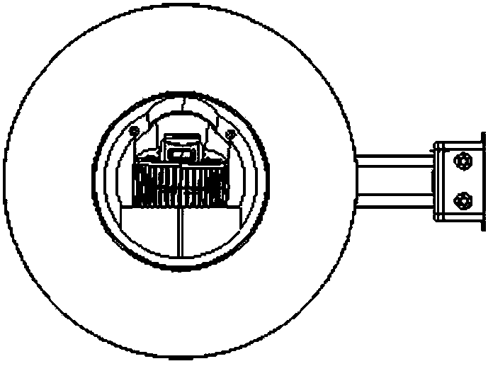
[0034] combine Figure 1 to Figure 4 , the anti-icing camera mainly includes: pan / tilt shell 1, fixing part 2, inverted U-shaped connection part 3, hemispherical cavity 4, observation window 5, infrared night vision lamp 6 and leeward shielding part 7, wherein,

[0035] The cloud platform shell 1 is a hemispherical or semi-ellipsoidal single-layer protective cover, which is fixedly linked at the top of the cover with the connection port of the fixing member 2 through a connection structure, and the cover mouth of the cloud platform shell 1 The end is provided with an edge stretching horizontally, preferably, the stretching length of the edge is 10-15cm; the fixing member 2 is a rectangular or trapezoidal profile structure with a rounded curve on one side, and the narrower end formed by the rounded curve The connection port is provided to connect with the pan-tilt shell 1, and the other end is fixed on the transmission line iron tower. The inverted U-shaped connection part 3 is...

Embodiment 2

[0042] In this embodiment, the structures and connections of the components of the anti-icing camera are the same as those in Embodiment 1, so they will not be described here again.

[0043] A heating device can also be set in the hemispherical cavity 4, which is connected with an external power supply by a wire, and is used to heat the hemispherical cavity 4 and the observation window 5, and the ice-coated surface on the surface of the hemispherical cavity 4 Melting and melting the residual icing on the surface of the observation window 5 that is not removed by the cleaning brush. Therefore, those skilled in the art can understand that, in order to transfer the heat energy of the heating device quickly and at the same time adapt to the alternation of cold and heat in a short period of time, the hemispherical cavity 4 is preferably made of metal material, of course, it can also have good thermal conductivity and can Materials suitable for alternating cold and heat in a short p...


PUM

PropertyMeasurementUnit
Diameteraaaaaaaaaa
Extended lengthaaaaaaaaaa
Angleaaaaaaaaaa

Abstract

The invention discloses an anti-icing vidicon. The anti-icing vidicon comprises a holder housing, a fixing piece, an inverted U-shaped connecting part, a semispherical cavity, an observation window, and a leeward shielding piece, wherein the holder housing is a semispherical or semi-ellipsoidal single-layer protective layer and fixedly connected with a connecting port of the fixing piece; an edge extending in a horizontal direction is arranged at the tail end of the cover port; the fixing piece is of a rectangular or trapezoidal section bar structure with a smooth curve at one end; the other end of the fixing piece is fixed on a power transmission wire iron tower; the inverted U-shaped connecting part is coaxially and movably connected to the top end in the cover of the holder housing, and arranged at the cover port of the holder housing; the semispherical cavity is horizontally fixed in the U-shaped opening of the inverted U-shaped connecting part; a camera head is arranged in the semispherical cavity; the observation window is arranged on the center of the circumferential surface of the semispherical cavity; a plurality of infrared night vision lamps are arranged at the two sides of the observation window; the leeward shielding piece is arranged on the back surface of the semispherical cavity. The anti-icing vidicon disclosed by the invention can be used for solving the problems that a camera is easy to ice and not resistant to low temperature when an icing phenomenon appears and that attachments on the surface of a lens or a transparent protective cover are difficult to clean.

Description

technical field [0001] The present application relates to the field of cameras, in particular to an anti-icing camera. Background technique [0002] In power transmission and transformation projects, the surface of the transmission wire in the power grid will freeze due to extreme low-temperature climates such as freezing rain, snowfall, and freezing, which is called icing. Icing is more common, and the faults caused by icing on transmission lines seriously affect the normal operation of the power system: icing can cause conductor galloping, tower tilting, collapse, disconnection and insulator flashover, resulting in major accidents. [0003] At present, in order to monitor the icing situation of the power transmission line in real time, a power video online monitoring device is installed in the transmission network to monitor the working status of the high-voltage transmission line, especially in natural disasters or extremely bad weather. The impact of line safety, to ach...

Claims


Application Information

Patent Timeline
IPC IPC(8): H04N5/225G03B17/55G03B17/56
Inventor 张雪峰姬红波董翀
Owner BEIJING GUOWANG FUDA SCI & TECH DEV
Why Eureka
Try Eureka