Heat pipe shell manufacturing method

A manufacturing method and shell technology, which are used in indirect heat exchangers, lighting and heating equipment, etc., can solve problems such as breakage, deformation of heat pipe shells, and difficulty in controlling accuracy, and achieve high shape freedom and prevent deformation.

Active Publication Date: 2013-10-30
迁安市彩旭杰汽车服务有限公司
View PDF5 Cites 8 Cited by
  • Summary
  • Abstract
  • Description
  • Claims
  • Application Information

AI Technical Summary

Problems solved by technology

However, it is difficult to control the accuracy of the bending or flattening process, and it is easy to cause deformation or even damage to the heat pipe shell, thereby affecting the heat conduction performance of the heat pipe

Method used


Image

  • Heat pipe shell manufacturing method
  • Heat pipe shell manufacturing method
  • Heat pipe shell manufacturing method

Examples


Embodiment Construction

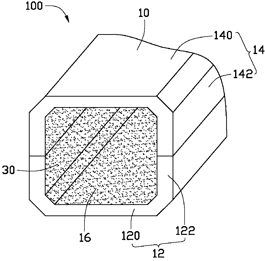
[0012] figure 1 It is a schematic axial cross-sectional view of an embodiment of the heat pipe of the present invention. The heat pipe 100 includes a housing 10 and a capillary structure 30 attached to the inner wall of the housing 10 .

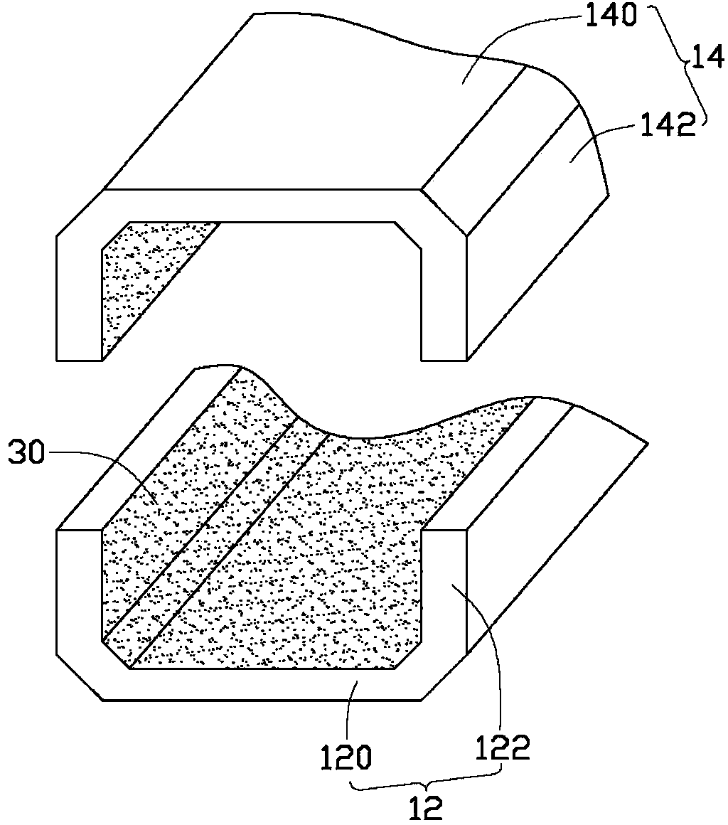
[0013] Please also see figure 2 , the cross-section of the housing 10 is flat, and it can be made of metal materials with good thermal conductivity such as copper or aluminum. The housing 10 includes a lower housing 12 and an upper housing 14 disposed on the lower housing 12 . The lower casing 12 includes a bottom wall 120 and two side walls 122 extending upward from two opposite sides of the bottom wall 120 . The upper housing 14 includes a top wall 140 corresponding to the bottom wall 120 of the lower housing 12 and two side walls 142 extending downward from opposite sides of the top wall 140 . The two sidewalls 142 of the upper casing 14 are fixedly connected with the two sidewalls 122 of the lower casing 12 to form a receiving space ...


PUM


Abstract

Disclosed is a heat pipe shell manufacturing method. The method includes the following steps: providing a mould; injecting a mixture of metal powder and melted binder into the mould by means of injection moulding to form a blank of an upper shell and a blank of a lower shell; removing the binder in the blank of the upper shell and the blank of the lower shell; sintering the blanks of the upper shell and the lower shell to obtain the upper shell and the lower shell; assembling the upper shell on the lower shell to form a shell. By the heat pipe shell manufacturing method, subsequent processing amount is effectively reduced, and manufacturing of high-melting-point, high-strength and complex-shape parts is facilitated better as compared with other forming modes.

Description

technical field [0001] The invention relates to a manufacturing method of a heat pipe shell. Background technique [0002] The heat pipe is widely used due to its characteristics of ultra-quiet, high thermal conductivity, light weight, small size, simple structure and multi-purpose. The space is in the state of a hollow body, and the working liquid is injected into the vacuumized airtight casing. Heat pipes are usually processed by bending or flattening a straight circular tube to produce shells of different shapes to meet various heat dissipation requirements. However, it is difficult to control the accuracy of the bending or flattening process, and it is easy to cause deformation or even damage to the heat pipe shell, thereby affecting the heat conduction performance of the heat pipe. Contents of the invention [0003] In view of this, it is necessary to provide a method for manufacturing the heat pipe housing with higher precision. [0004] A method for manufacturing...

Claims


Application Information

Patent Timeline
Patent Type & Authority Applications(China)
IPC IPC(8): B22F3/22B22F3/20B22F3/11B22F5/00F28D15/02
Inventor 钟明修郑年添
Owner 迁安市彩旭杰汽车服务有限公司
Why Eureka
Try Eureka