Unlock instant, AI-driven research and patent intelligence for your innovation.

Transmission device

A transmission and drive technology, applied in transmissions, engines, machines/engines, etc., can solve problems such as insurmountable, non-long-term price stability, unstable power source, etc., and achieve the effect of reducing energy loss

Inactive Publication Date: 2013-10-30
JUN DONG POWER
View PDF5 Cites 0 Cited by
  • Summary
  • Abstract
  • Description
  • Claims
  • Application Information

AI Technical Summary

Problems solved by technology

[0006] However, the above-mentioned types of rotating power generation methods have many shortcomings, which are difficult to overcome.
[0007] 1. The power source is unstable, such as hydropower, wind power, etc.
[0008] 2. The supply and cost of raw materials are high, the price is not stable for a long time, and the earth reserves are limited
[0009] 3. Serious damage to the natural environment and ecology during construction and operation
[0010] 4. After operation, the aftermath cost of equipment maintenance and pollution is difficult to calculate
[0011] 5. High security doubts, such as radiation disasters caused by nuclear power generation

Method used


Image

  • Transmission device
  • Transmission device
  • Transmission device

Examples


Embodiment Construction

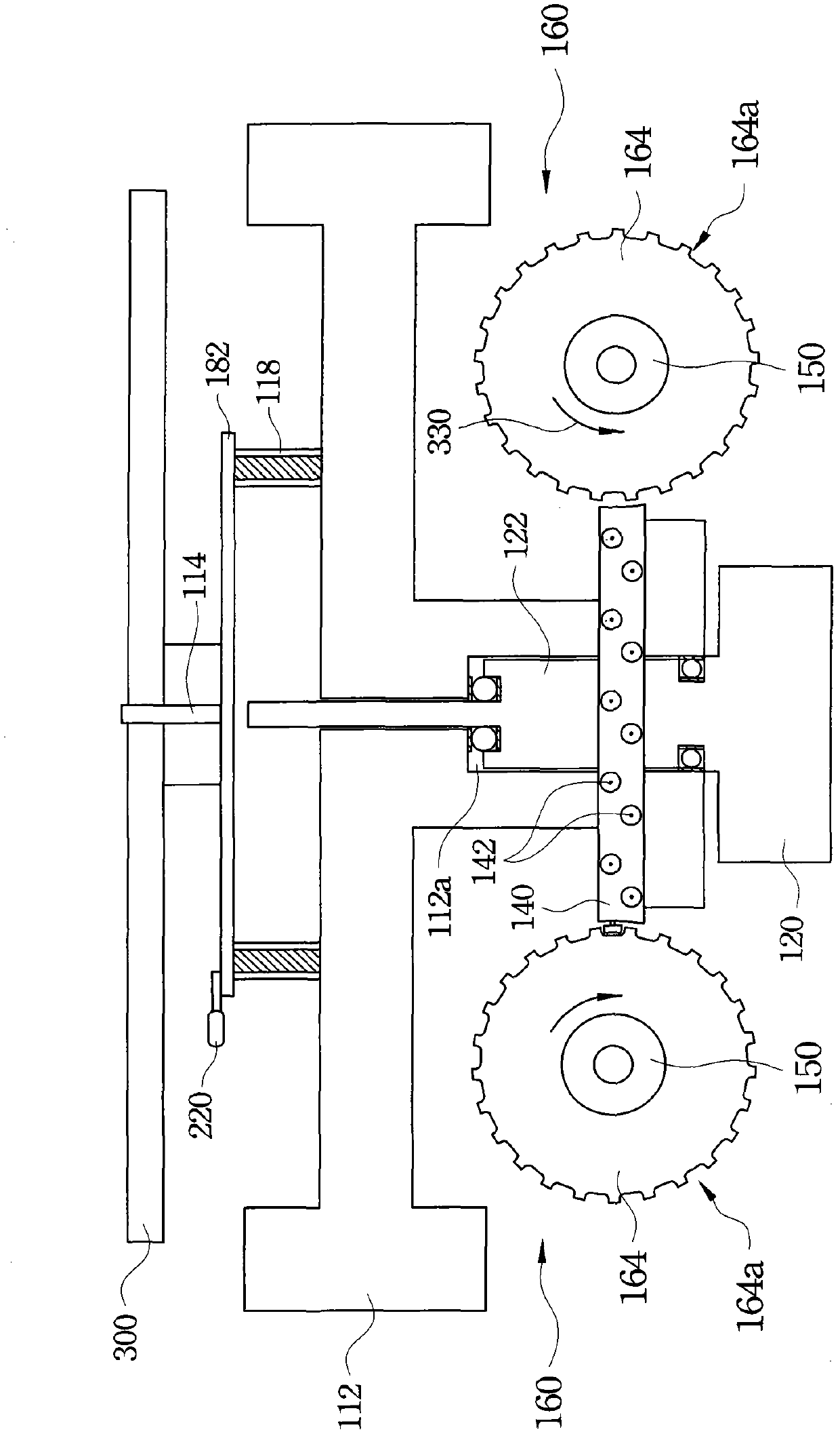
[0053] figure 1 Shows a cross-sectional view of a transmission device according to an embodiment of the present invention, figure 2 Then figure 1 Top view of the gearing. As shown in the figure, a transmission device mainly includes a gyro gravity body 112, a driving device 200, a transmission disc 140 and a rotating wheel 164.

[0054] As mentioned above, a gear ring 182 is provided on the gyro gravity body 112, which is arranged on the top of the gyro gravity body 112 with the rotating shaft 114 as a center, and the gear ring 182 is fixed on the gyro gravity body 112 by a connecting ring 118. The rotating shaft 114 penetrates the central axis of the top gravity body 112 and is substantially perpendicular to the ground. In other words, the gyroscopic gravity body 112 rotates along a rotation axis 114 perpendicular to the ground.

[0055] The rotating shaft 114 extends upward from the central column 122 of the base 120. The central groove 112 a of the gyro-gravity body 112 is sl...


PUM


Abstract

The invention discloses a transmission device. The transmission device comprises a top gravity body, a drive device, a transmission disc and a generator module. The drive device is used for driving the top gravity body to rotate along a rotary shaft perpendicular to the ground. The transmission disc is fixed on the top gravity body, rotates with the top gravity body synchronously and is provided with multiple rolling part groups located on the side edge, wherein each rolling part group is provided with at least two rolling parts. The generator module is provided with a rotating wheel, wherein the rotating wheel is provided with multiple oblique tooth grooves located on the side edge, and each oblique tooth groove is used for a corresponding rolling part group on the transmission disc to be meshed in so as to enable transmission disc to drive the rotating wheel to rotate. Connecting lines of the circle centers of rolling parts of each rolling part group are parallel to the side walls of corresponding oblique tooth grooves. Angles formed by the connecting lines of the circle centers of the rolling parts of each rolling part group and a horizontal plane are larger 0 degree and smaller than 45 degrees.

Description

Technical field [0001] The invention relates to a gravity or inertial generator. Background technique [0002] In terms of power generation technology, the current global power generation technology can be roughly summarized into rotating power generation and non-rotating power generation. In terms of rotating power generation, it mainly includes the following methods: [0003] 1. Hydroelectric power generation: the potential energy of water is transformed into potential energy, and the turbine is driven, transformed into mechanical energy, and then into electrical energy. [0004] 2. Thermal power generation: Containing geothermal, oil, coal, natural gas, nuclear energy, solar energy, etc., the thermal energy is converted into mechanical energy, and then the generator is turned to generate electrical energy. [0005] 3. Wind power generation: using wind power to rotate a generator to generate electricity. [0006] However, the above-mentioned types of rotary power generation methods h...

Claims


Application Information

Patent Timeline
IPC IPC(8): F03G3/00F16H33/02
Inventor 蔡名竣
Owner JUN DONG POWER
Features
  • R&D
  • Intellectual Property
  • Life Sciences
  • Materials
  • Tech Scout
  • Unparalleled Data Quality
  • Higher Quality Content
  • 60% Fewer Hallucinations
Learn More