Complete passive cooling system for post-accident reactor cores of large PWR (pressurized water reactor) nuclear power plants

A pressurized water reactor nuclear power plant, passive cooling technology, applied in nuclear power generation, cooling devices, nuclear engineering, etc., can solve problems such as leakage of radioactive materials, inability to discharge residual heat from the core, core melting, etc., to maintain integrity , Improving the anti-aircraft impact ability and simplifying the structure

Inactive Publication Date: 2013-10-30
SHANGHAI NUCLEAR ENG RES & DESIGN INST CO LTD
View PDF6 Cites 11 Cited by
  • Summary
  • Abstract
  • Description
  • Claims
  • Application Information

AI Technical Summary

Problems solved by technology

[0002] On March 11, 2011, a nuclear accident that shocked the world occurred in Fukushima, Japan. One of the main reasons for the nuclear accident was that under the super design basis accident of the earthquake and tsunami, the GE company owned by Fukushima produced The Mark I unit could not realize the effective removal of waste heat from the core, which eventually caused the core to melt and produce...

Method used


Image

  • Complete passive cooling system for post-accident reactor cores of large PWR (pressurized water reactor) nuclear power plants
  • Complete passive cooling system for post-accident reactor cores of large PWR (pressurized water reactor) nuclear power plants
  • Complete passive cooling system for post-accident reactor cores of large PWR (pressurized water reactor) nuclear power plants

Examples


Embodiment 1

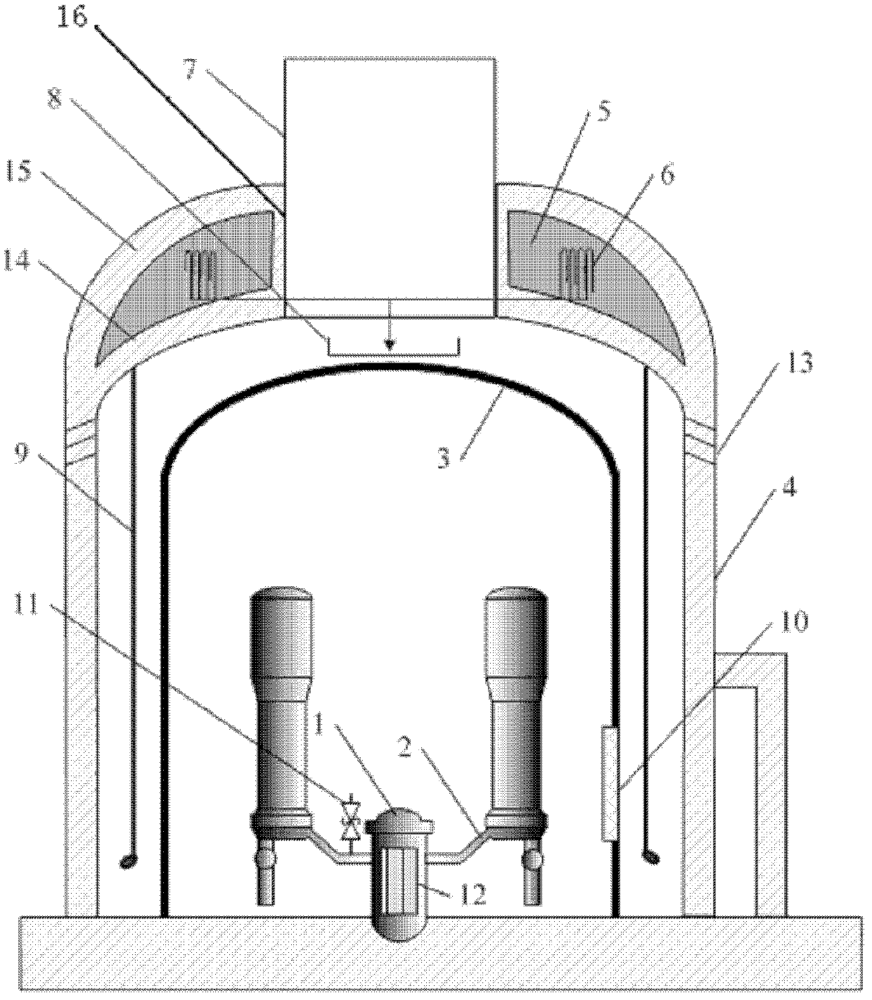
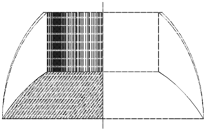
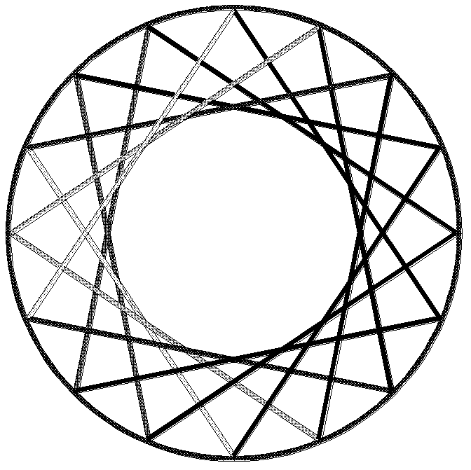
[0024] Such as figure 1 As shown, the shielded factory building 4 is a steel-concrete composite structure, including a cylindrical cylinder and a double-layer structure top. The top of the double-layer structure is formed at the upper end of the cylindrical cylinder, and the top of the double-layer structure includes an inner shell 14 , the housing 15 and the air channel 16. Shield the steel frame on the top of plant building 4, such as figure 2 , 3As shown in and 4, the inner shell 14 is a semi-ellipsoid arch shell, and its semi-ellipsoid arch shell is set on a tensile stress ring beam; the outer shell 15 is a hemispherical arch shell, and its hemispherical arch shell is set on another tensile stress ring beam. stress ring beam. Taking the tensile stress ring beam of the inner shell 14 as the outer circle, and the air flow channel 16 as the inner circle, semi-elliptical arch beams are evenly arranged around the center of the circle at equal angles, and the semi-elliptical...

Embodiment 2

[0026] Such as Figure 5 As shown, the difference from Embodiment 1 is that the inner shell 14 on the top of the shielding plant 4 is conical, and the outer shell 15 is the top of a double-layer steel-concrete composite structure that is cylindrical, and the opening of the cylindrical steel-concrete composite structure is air. The flow channel 16, the cavity formed between the inner shell 14, the outer shell 15 and the air flow channel 16 is the water tank 5, that is, the top of the double-layer steel-concrete composite structure forms the water tank 5. The steel-concrete composite structure of the shielding workshop 4 adopts the compression ring design in the prior art. A cooling water distribution plate 8 is arranged on the top of the containment 3 and in the middle of the shielding building 4 , and the cooling water distribution plate 8 is suspended on the pressure ring of the shielding building 4 .

Embodiment 3

[0028] Such as Figure 6 As shown, the difference from Embodiment 1 is that the top inner shell 14 of the shielded factory building 4 is semi-ellipsoidal, and the outer shell 15 is the top of the double-layer steel-concrete composite structure of the cylindrical shape, and the cylindrical steel-concrete composite structure opening is formed as the air at the same time. The flow channel 16, the cavity formed between the inner shell 14, the outer shell 15 and the air flow channel 16 is the water tank 5, that is, the top of the double-layer steel-concrete composite structure forms the water tank 5. A cooling water distribution plate 8 is installed on the top of the steel containment vessel 3 and in the middle of the shielded building 4 , and the cooling water distribution plate 8 is suspended on the arched shell of the inner shell 14 .

[0029] When an accident occurs in the reactor, if the pressure vessel 1 is ruptured or the pressure boundary 2 of the primary circuit is rupture...


PUM


Abstract

A completely passive cooling system for a post-incident reactor core of a large-scale pressurized water reactor nuclear power plant, comprising a shielded plant (4), a water tank (5), a cooling water distribution plate (8), a sprinkler water pipe (6), and an air deflector panel (9). A chimney (7) is arranged on the top part of the steel-concrete composite structured shielded plant (4). The water tank (5) is arranged above the shielded plant (4) and around the chimney (7). The cooling water distribution plate (8) is arranged above the top part of a safety housing (3) within the shielded plant (4). The sprinkler water pipe (6) is arranged on the inside of the top part of the shielded plant (4). A water inlet-end of the sprinkler water pipe (6) is connected to the bottom part of the water tank (5). A water outlet-end of the sprinkler water pipe (6) is extended above the cooling water distribution plate (8). A through air inlet (13) is provided on the top part of an outer wall of the shielded plant (4). The air deflector panel (9) is arranged between the shielded plant (4) and the safety housing (3). The upper end of the air deflector panel (9) is connected to the inside of the top part of the shielded plant (4). A double-layered top part is formed on the upper end of the cylindrical shielded plant (4), while a cylindrical air flow passage (16) is formed on the top part, where the double-layered steel-concrete top part constitutes the water tank (5). The cooling system employs the integrated modular design of the shielded plant (4) and the water tank (5), and enlarges the volume of the water tank (5), thus implementing long-term completely passive discharge of reactor core residual heat.

Description

technical field [0001] The invention relates to the field of dedicated safety systems for pressurized water reactor nuclear power plants, in particular to a completely passive cooling system for cores after accidents in large pressurized water reactor nuclear power plants. Background technique [0002] On March 11, 2011, a nuclear accident that shocked the world occurred in Fukushima, Japan. One of the main reasons for the nuclear accident was that under the super design basis accident of the earthquake and tsunami, the GE company owned by Fukushima produced The Mark I unit could not realize the effective discharge of waste heat from the core, which eventually caused the core to melt and produce a large amount of hydrogen, which indirectly caused the overpressure of the containment. After the Fukushima incident, nuclear power safety agencies and industry have a stronger demand for long-term passive cooling capacity of nuclear power plants. The Japan Atomic Energy Associatio...

Claims


Application Information

Patent Timeline
IPC IPC(8): G21C15/18
CPCY02E30/32G21C9/00G21C15/18Y02E30/40G21C9/004G21C13/02Y02E30/30
Inventor 郑明光叶成葛鸿辉董宪康顾国兴严锦泉苗富足王勇叶元伟陈煜夏祖讽邱健凌云
Owner SHANGHAI NUCLEAR ENG RES & DESIGN INST CO LTD
Why Eureka
Try Eureka