
A wet spent fuel storage system

A spent fuel, wet technology, used in the field of spent fuel storage in nuclear power plants, can solve the problems of poor reliability of the cooling system and achieve the effect of reliable operation

Active Publication Date: 2015-12-02
SHANGHAI NUCLEAR ENG RES & DESIGN INST CO LTD
View PDF5 Cites 0 Cited by
  • Summary
  • Abstract
  • Description
  • Claims
  • Application Information

AI Technical Summary

Problems solved by technology

This method relies on the power supply to drive the pump, and needs to continuously provide cooling water source. The reliability of the cooling system is poor under severe accidents.

Method used


Image

  • A wet spent fuel storage system
  • A wet spent fuel storage system

Examples


Embodiment Construction

[0014] In order to understand the present invention more clearly, the present invention will be further described below in conjunction with the accompanying drawings.

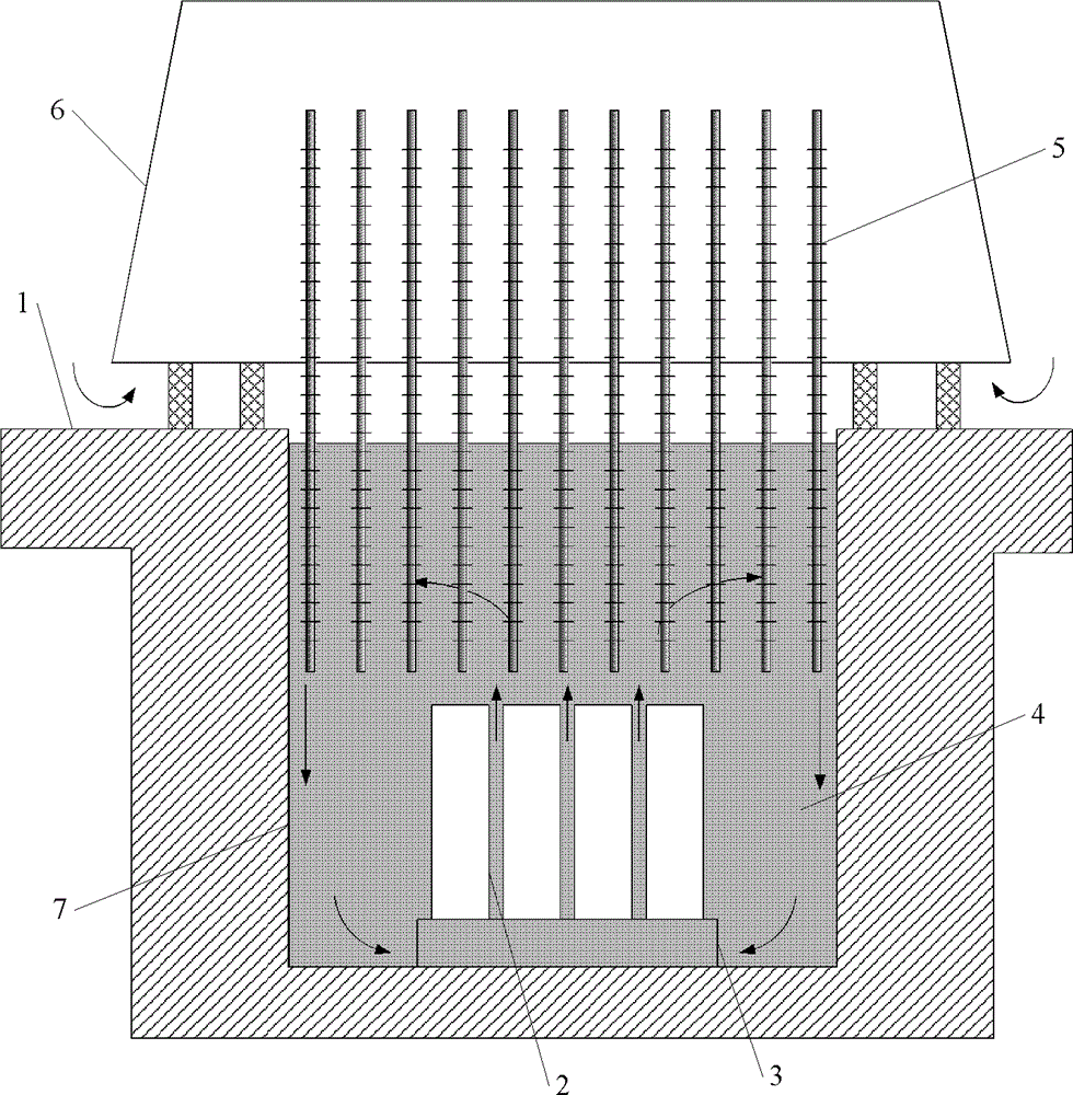
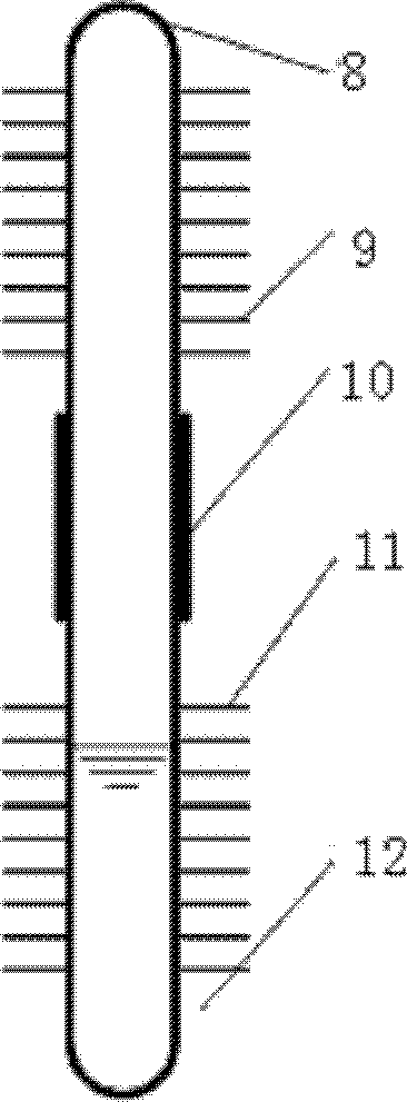
[0015] like figure 1 As shown, a wet-type spent fuel storage device includes a sealed container 2, a spent fuel storage grid 3, a cooling liquid 4, a heat pipe cooling device 5, an air cooling tower 6 and a spent fuel storage pool 7, and cement is built under the ground 1 The spent fuel storage pool 7 is used as the spent fuel storage pool 7, and the spent fuel storage pool 7 is filled with a cooling liquid 4, and the cooling liquid 4 is made of cheap water or a lithium bromide liquid that is difficult to volatilize and has a very high boiling point. The spent fuel storage grid 3 is placed at the bottom area of ​​the spent fuel storage pool 7. The spent fuel storage grid 3 adopts the existing technology to meet the requirements of shock resistance and strength and provide sufficient support. The spent fuel asse...


PUM


Abstract

The invention relates to a wet-type spent fuel storage system, belonging to the field of nuclear power station spent fuel storage. The invention implements long-time storage of spent fuel by adopting a non-kinetic mode. A spent fuel storage grid is arranged on the bottom of a spent fuel storage pool which contains a coolant; a sealed container carrying a spent fuel assembly is arranged on the spent fuel storage grid; an air cooling tower is arranged on the upper part of the spent fuel storage pool; one end of a heat-tube cooling unit is arranged in the air cooling tower; and the other end of the heat-tube cooling unit is immersed in the coolant of the spent fuel storage pool. By utilizing the decay heat generated by the spent fuel to drive the separate cooling unit without external driving force, the invention implements natural circulation of the coolant in the spent fuel storage pool; the invention implements the long-time storage of the spent fuel in a non-kinetic mode, and has the advantage of reliable operation.

Description

technical field [0001] The invention relates to the technical field of nuclear power plant spent fuel storage, in particular to a wet spent fuel storage system using liquid as an intermediate heat sink. Background technique [0002] For general pressurized water reactor nuclear power plants, the refueling cycle is usually 12-18 months, and the spent fuel that is replaced is generally stored in the spent fuel pool of the auxiliary plant for several years, until the decay heat of the spent fuel is reduced , and then transport the spent fuel away. At present, the decay heat export of the spent fuel storage pool is mainly realized through the decay heat export system of the spent fuel storage pool. Under the action of the pump, the water is pumped out from the spent fuel storage pool and then reaches the external heat exchanger. In this heat exchanger, it is cooled by cooling water, thereby removing heat. This method relies on the power supply to drive the pump, and needs to co...

Claims


Application Information

Patent Timeline
Patent Type & Authority Patents(China)
IPC IPC(8): G21C19/07
CPCY02E30/30
Inventor 郑明光叶成顾国兴张荣华蔡强郑利民干富军
Owner SHANGHAI NUCLEAR ENG RES & DESIGN INST CO LTD
Learn More