Substrate conveyance roller, thin film manufacturing device and thin film manufacturing method

A substrate conveying and substrate technology, which is applied in the direction of transportation and packaging, roller table, vacuum evaporation coating, etc., can solve the problem of not being able to maintain the vacuum

Inactive Publication Date: 2013-10-30
PANASONIC CORP
View PDF4 Cites 8 Cited by
  • Summary
  • Abstract
  • Description
  • Claims
  • Application Information

AI Technical Summary

Problems solved by technology

[0007] However, in a vacuum atmosphere, the vacuum cannot be maintained by using a large flow rate of gas to the extent that the heat is directly taken away by the cooling gas.

Method used


Image

  • Substrate conveyance roller, thin film manufacturing device and thin film manufacturing method
  • Substrate conveyance roller, thin film manufacturing device and thin film manufacturing method
  • Substrate conveyance roller, thin film manufacturing device and thin film manufacturing method

Examples


Embodiment approach 1)

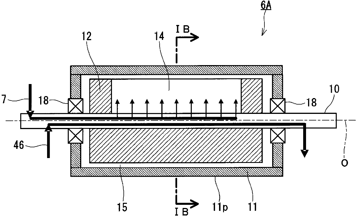
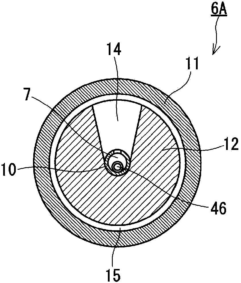
[0082] Below, refer to Figure 1A as well as Figure 1B Embodiment 1 of the present invention will be described. The self-cooling gas roll according to this embodiment is schematically shown in Figure 1A as well as Figure 1B middle.

[0083] Such as Figure 1A as well as Figure 1B As shown, the self-cooling gas roll 6A has a first housing 11 that rotates synchronously with the substrate, an inner block 12 that does not rotate synchronously with the substrate, and a shaft 10 that supports the inner block 12 . The first case 11 has a cylindrical outer peripheral surface 11p for supporting the substrate. The inner block 12 is arranged inside the first casing 11 . The inner block has a cylindrical or cylindrical shape as a whole. The shaft 10 passes through the inner block 12 and supports the inner block 12 . The shaft 10 and the central axis O of the inner block 12 coincide with the central axis O (rotational axis) of the first housing 11 .

[0084] The first housing 11...

Embodiment approach 2)

[0123] Next, refer to Figure 3A , Figure 3B , Figure 4A as well as Figure 4B The second embodiment will be described. The same reference numerals are attached to the same components as those described in the previous embodiment, and description thereof will be omitted.

[0124] In this embodiment, if Figure 3A , Figure 3B , Figure 4A as well as Figure 4B As shown, the manifold is formed from a plurality of manifolds 14 . In this way, if a plurality of manifolds 14 are formed, the conductivity of each gas flow path (manifold 14 ) can be set independently. A plurality of manifolds 14 are arranged in the width direction of the inner block 12 .

[0125] By adjusting the pressure distribution in the gap portion 15 in the width direction of the substrate in this way, the intensity of the gas cooling can be changed.

[0126] For example, in the formation of a thin film using a vacuum process, the thermal load received by the central portion of the substrate in the w...

Embodiment approach 3)

[0134] Next, refer to Figure 5A and Figure 5B The third embodiment will be described. The same reference numerals are attached to the same components as those described in other embodiments, and description thereof will be omitted.

[0135] Such as Figure 5A and Figure 5B As shown, in the self-cooling gas roll 6E, the inner block 12 is composed of a plurality of divided blocks 16 divided by manifolds 14 arranged in the width direction of the substrate. The plurality of division blocks 16 respectively correspond to the plurality of manifolds 14 .

[0136] Furthermore, the first housing 11 is constituted by a plurality of divided housings 17 corresponding to the divided blocks 16 .

[0137] By dividing the inner block 12 and the first casing 11 into a plurality, the structure of the self-cooling gas roller corresponding to desired cooling conditions can be easily obtained by reorganizing the divided block 16 and / or the divided casing 17 . In addition, the machining acc...


PUM

PropertyMeasurementUnit
diameteraaaaaaaaaa

Abstract

A substrate-conveying roller 6A is configured to convey a substrate under vacuum, and includes a first shell 11, an internal block 12, and a shaft 10. The first shell 11 has a cylindrical outer circumferential surface for supporting the substrate, and can rotate in synchronization with the substrate. The internal block 12 is disposed inside the first shell 11, and is blocked from rotating in synchronization with the substrate. The shaft 10 extends through, and supports the internal block 12. A clearance 15 is formed between the inner circumferential surface of the first shell 11 and the internal block 12. A gas is introduced into the clearance 15 from the internal block 12 toward the inner circumferential surface of the first shell 11.

Description

technical field [0001] The present invention relates to a substrate conveying roller, a film manufacturing device, and a film manufacturing method. Background technique [0002] Thin-film technology is being widely developed for high performance and miniaturization of devices. In addition, the thinning of devices is not limited to direct advantages for users, but also plays an important role from environmental aspects such as conservation of earth resources and reduction of power consumption. [0003] In the development of such a thin film technology, it is necessary to meet the demands of industrial utilization such as high efficiency, stabilization, high productivity, and cost reduction of thin film manufacturing methods, and efforts are being made to meet these demands. [0004] In order to improve the productivity of the thin film, a film-forming technology with a high deposition rate is required. In the production of thin films represented by vacuum evaporation, sputt...

Claims


Application Information

Patent Timeline
Patent Type & Authority Applications(China)
IPC IPC(8): C23C14/56
CPCC23C16/458C23C16/4581C23C16/545C23C16/466B65G13/00C23C14/562C23C14/541C23C14/50C23C16/463
Inventor 本田和义冈崎祯之天羽则晶内田纪幸末次大辅
Owner PANASONIC CORP
Why Eureka
Try Eureka