Dye-sensitized solar cell for low light intensities

A solar cell and dye sensitization technology, which is applied in the field of dye-sensitized solar cells for low illumination, can solve the problems of current and voltage drop of dye-sensitized solar cells, reduction of photoelectric conversion efficiency, drop of open circuit voltage and the like

Inactive Publication Date: 2013-10-30
THE FUJIKURA CABLE WORKS LTD
View PDF5 Cites 0 Cited by
  • Summary
  • Abstract
  • Description
  • Claims
  • Application Information

AI Technical Summary

Problems solved by technology

[0005] However, it is generally known that the generated current and generated voltage of the dye-sensitized solar cell decrease under low-illuminance (less than 10,000 lux) environments such as indoors.
This is because the amount of incident light decreases, resulting in a decrease in short-circuit current, and leakage current occurs between the oxide semiconductor layer as the power ge

Method used


Image

  • Dye-sensitized solar cell for low light intensities
  • Dye-sensitized solar cell for low light intensities
  • Dye-sensitized solar cell for low light intensities

Examples


Embodiment 1

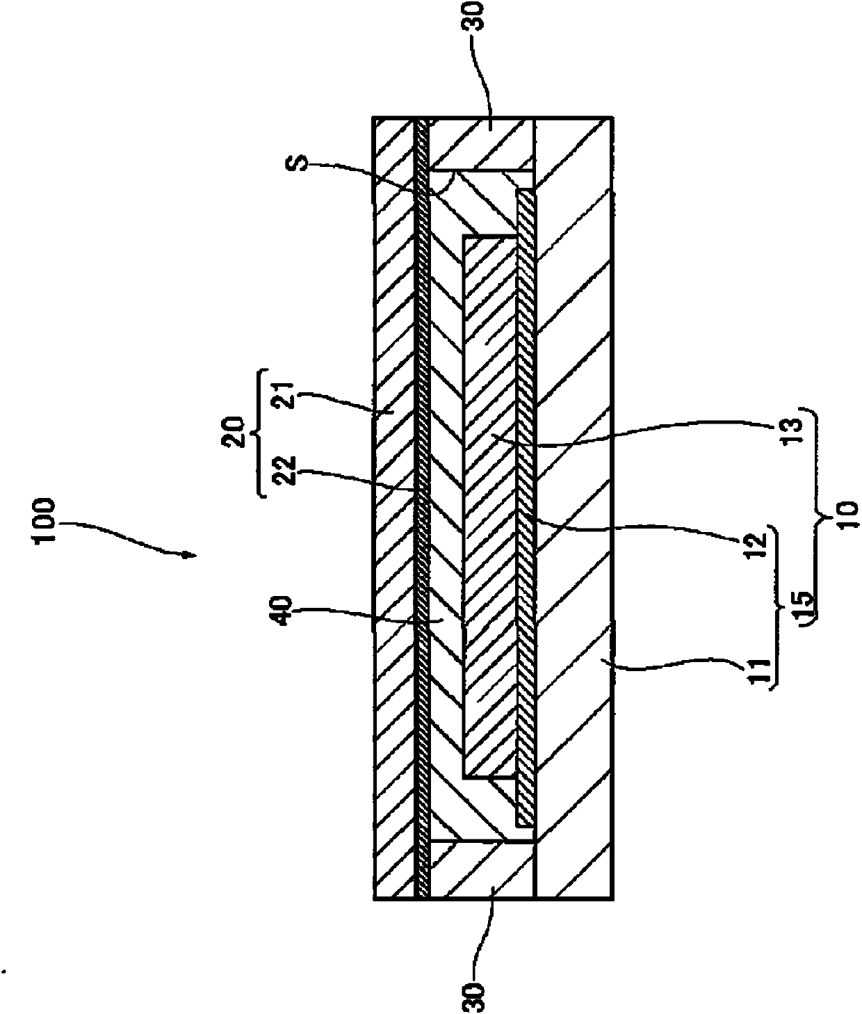
[0216] First, a transparent conductive substrate formed by forming a transparent conductive film made of FTO with a thickness of 1 μm on a transparent substrate made of glass with a thickness of 1 mm was prepared. Then, patterning was performed with a CO2 laser (V-460, a product of Universal System Co., Ltd.) to form four transparent conductive films arranged in a row. By patterning, each of the four transparent conductive films had a rectangular body part of 3 cm x 5 cm, and the interval between the body parts was 0.5 mm. In addition, for 3 transparent conductive films among the 4 transparent conductive films, two protruding parts are respectively formed from the two sides of the main body part, and from the two protruding parts are respectively formed to extend to the adjacent The DSC corresponds to the extension of the position on the side opposite to the side of the main body of the transparent conductive film. At this time, the length of the extending portion in the exte...

Embodiment 2~22 and comparative example 1~6

[0228] In addition to the photosensitizing dye, co-adsorbent 1, co-adsorbent 2 and I 3 - The DSC module was prepared in the same manner as in Example 1, except that the concentration (unit: μM) was changed as shown in Table 1 and Table 2.

Embodiment 23 and 24

[0230] In addition to the photosensitizing dye, co-adsorbent 1, co-adsorbent 2 and I 3 - The DSC module was prepared in the same manner as in Example 1, except that the concentration (unit: μM) was changed as shown in Table 2. At this time, the molar ratio of the co-adsorbent 2 to the co-adsorbent 1 was 3.

[0231] As shown in Table 1 and Table 2, the open voltage Voc at 100 lux and the photoelectric conversion efficiency were measured for the DSC modules obtained in Examples 1 to 24 and Comparative Examples 1 to 6. Here, the photoelectric conversion efficiency η was measured under the conditions of illuminance of 10 lux, 100 lux, 1000 lux, 10000 lux, and 20000 lux, respectively. The results are shown in Table 1 and Table 2.

[0232] As shown in Table 1 and Table 2, for the DSC modules obtained in Examples 1 to 24, under the illuminance of 100 lux (measurement light source is a fluorescent lamp), there is a lower open voltage than the DSC modules obtained in Comparative Exa...


PUM

PropertyMeasurementUnit
Thicknessaaaaaaaaaa
Thicknessaaaaaaaaaa
Thicknessaaaaaaaaaa

Abstract

The present invention is a dye-sensitized solar cell for low light intensities which is provided with: a first electrode, which has a transparent substrate and a transparent conductive film provided on the transparent substrate; a second electrode, which faces the first electrode; an oxide semiconductor layer, which is provided on the first electrode or the second electrode; an electrolyte, which is provided between the first electrode and the second electrode; a photosensitization dye, which is adsorbed to the oxide semiconductor layer; and a co-adsorption agent which is adsorbed to the oxide semiconductor layer together with the photosensitization dye. Therein, the photosensitization dye is a metal-complex compound represented by formula (1), and the co-adsorption agent includes an organic compound represented by formula (2), or similar. (In formula (1) M represents Ru, R1, R2, R3 and R4 each independently represents a monovalent cation, and R5 and R6 each independently represents a halogen group, or similar.) (In formula (2) n represents an integer 0-5, and R7 represents a monovalent group having a p-conjugated structure, or similar.)

Description

technical field [0001] The present invention relates to dye-sensitized solar cells for low illumination. Background technique [0002] As a photoelectric conversion element, a dye-sensitized solar cell has attracted attention because it can obtain low-cost and high photoelectric conversion efficiency, and various developments have been made on the dye-sensitized solar cell. [0003] A dye-sensitized solar cell generally includes a working electrode, a counter electrode, a sealing part connecting the working electrode and the counter electrode, and an electrolyte filled in a unit cell space surrounded by the working electrode, the counter electrode and the sealing part. Also, the working electrode includes a transparent substrate, a transparent conductive film provided on the transparent substrate, and an oxide semiconductor layer as a power generation layer provided on the transparent conductive film. [0004] In recent years, dye-sensitized solar cells have been used not o...

Claims


Application Information

Patent Timeline
IPC IPC(8): H01M14/00H01L31/04
CPCH01M14/00H01L51/0059H01L51/0086H01G9/2059H01L51/0077H01L31/04Y02E10/50H01G9/2063H01G9/2031Y02E10/542H10K85/631H10K85/30H10K85/344
Inventor 下平幸辉冈田显一远藤克佳
Owner THE FUJIKURA CABLE WORKS LTD
Why Eureka
Try Eureka