Clutter suppression method suitable for high pulse repetition frequency (HPRF) waveform airborne radar

An airborne radar and clutter suppression technology, applied in the radar field, can solve the problems of the actual detection error of the radar, the unsatisfactory clutter suppression performance, and the degraded clutter suppression performance, so as to achieve the effect of improving reliability.

Active Publication Date: 2013-11-06
XIDIAN UNIV
View PDF5 Cites 26 Cited by
  • Summary
  • Abstract
  • Description
  • Claims
  • Application Information

AI Technical Summary

Problems solved by technology

In the case of known radar system configuration parameters, compensation algorithms can be used to compensate the distance dependence of clutter caused by front configuration, including Doppler frequency shift algorithm and angle Doppler compensation algorithm, Doppler frequency shift algorithm It is to calculate the main clutter Doppler frequency of the unit to be detected and each reference unit according to the radar system parameters, and then shift a complex phase factor for each reference unit along the time domain direction, so that the Doppler frequency of the clutter spectrum of each reference unit after compensation The frequency center is the same as the Doppler frequency center of the unit to be detected; the angle Doppler compensation algorithm is a two-dimensional translation along the space domain and time domain, and moves the center of the clutter spectrum of the reference unit along the angle-Doppler direction to the clutter of the unit to be detected. The position of the spectral center, so that the angle-Doppler center of the main clutter of each reference unit coincides with the angle-Doppler center of the unit to be tested, but these compensation algorithms are only suitable for the case of no distance ambiguity, that is, the ideal situation, but in reality, a...

Method used


Image

  • Clutter suppression method suitable for high pulse repetition frequency (HPRF) waveform airborne radar
  • Clutter suppression method suitable for high pulse repetition frequency (HPRF) waveform airborne radar
  • Clutter suppression method suitable for high pulse repetition frequency (HPRF) waveform airborne radar

Examples


Embodiment 1

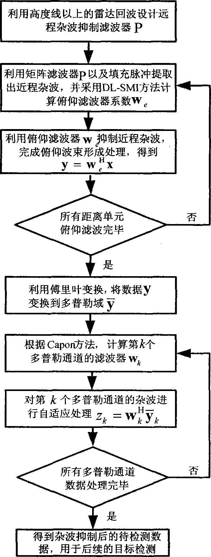
[0048] The invention is a clutter suppression method suitable for HPRF waveform airborne radar. The HPRF waveform airborne radar is a radar that utilizes a higher pulse repetition frequency to obtain a larger Doppler space area, so it can be used to detect motion The air target is relatively fast, but the unambiguous range of this kind of radar is relatively short, while the radar's line of sight is long, so there are generally multiple range ambiguities, especially under the condition of non-frontal array airborne radar, the short-distance The clutter and long-distance clutter overlap together, and the clutter is difficult to suppress, making it difficult to distinguish the target. Suppressing the clutter in the radar echo is an important prerequisite for the successful detection of the target by the HPRF waveform radar, so it is a problem that must be solved. The invention is aimed at suppressing the clutter of the non-frontal array airborne radar, and the non-frontal array a...

Embodiment 2

[0074] Applicable to the HPRF waveform airborne radar clutter suppression method is the same as embodiment 1, wherein the pitch filter w is calculated in step (7) k Including the following steps:

[0075] (7a) Take out The data of the k-th Doppler channel and its adjacent two Doppler channels, and the data of the three Doppler channels are sequentially connected into a linear array data block in the following form in i=k-1, k, k+1 represent the data of all range units of all array elements in the i-th Doppler channel, its dimension is N×L, N is the number of azimuth array elements, and L is all range units number, the line array data is the data that has filtered out the short-range clutter, but it also contains the long-range clutter.

[0076] (7b) Using the maximum likelihood method, estimate the space-time covariance matrix of the kth Doppler channel R ^ k = y ...

Embodiment 3

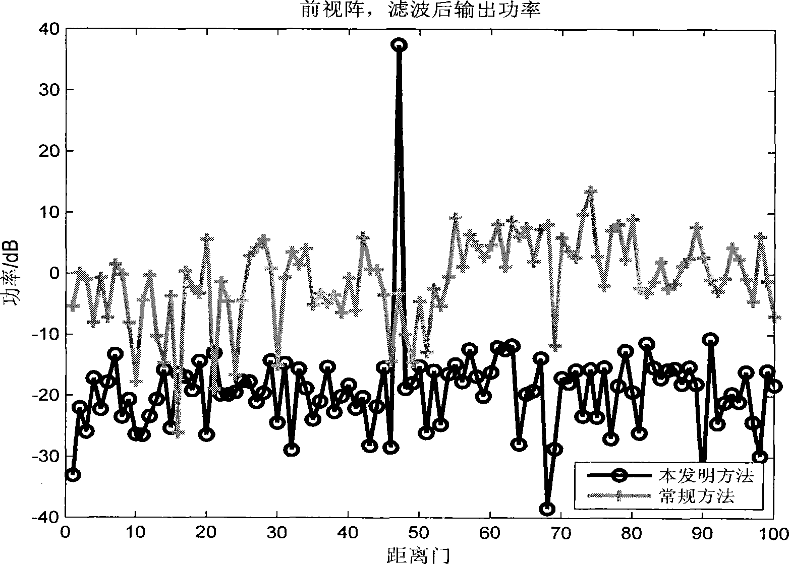
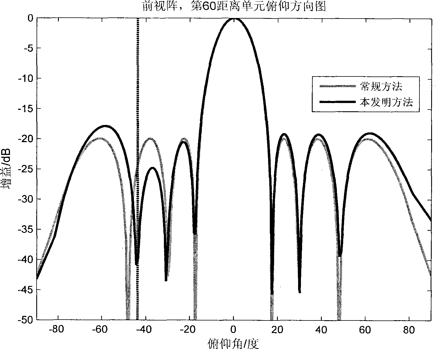
[0080] The method applicable to HPRF waveform airborne radar clutter suppression is the same as that in Embodiment 1-2, and the advantages of the present invention can be illustrated through the forward-looking array airborne radar clutter suppression simulation experiment.

[0081] 1. Experimental parameters and experimental conditions

[0082] The radar antenna adopts a forward-looking planar array of 8 rows×16 columns. The radar emission wavelength is 0.1 meters, and the array element spacing is 0.05 meters. It transmits 32 pulses within a coherent pulse repetition interval CPI, and the pulse repetition frequency is 6200Hz. The system bandwidth The frequency is 2MHz, the main beam points to the normal direction of the front, and the noise-to-noise ratio (CNR) is 45dB; the altitude of the carrier aircraft is 4150 meters, and the flight speed of the carrier aircraft is 130m / s. The radar illuminates a target whose distance from the radar is 391.86Km (the 47th range gate), the ...


PUM


Abstract

The invention discloses a clutter suppression method suitable for a high pulse repetition frequency (HPRF) waveform airborne radar. The clutter suppression method comprises the steps of utilizing remote echo data above an nth array element altitude line to evaluate a long-distance main-lobe clutter Q, and utilizing Q to design a matrix filter P so as to extract short range clutter; utilizing P to extract short range clutter in first distance unit data xln of an nth array element, and estimating a short range clutter covariance matrix to adopt an opposite angle loading sampling covariance inversion method to calculate a pitching filter we; utilizing we to suppress short range clutter in xln, and obtaining data Y not containing short range clutter after all the data are processed; performing conversion from a pulse domain to a Doppler domain; taking out data from the Doppler domain and estimating a clutter suppression filter wk; utilizing the filter to suppress remote clutter, processing all Doppler channel data, and outputting to-be-detected data to be used for follow-up radar monitoring processing. According to the clutter suppression method, clutter suppression is achieved in the presence of array errors, the short range clutter can be suppressed well, industrialized achievement is easy, and target detection performance of the airborne radar can be remarkably improved.

Description

technical field [0001] The invention belongs to the technical field of radar and relates to clutter suppression of airborne radar, in particular to a clutter suppression method suitable for high pulse repetition frequency (HPRF) waveform airborne radar, used for clutter suppression of planar array radar with HPRF waveform wave suppression. Background technique [0002] Space-time adaptive processing (STAP) technology can effectively detect targets in complex ground clutter environments. According to the RMB criterion, when the number of training samples satisfying the independent and identically distributed condition is twice the system degree of freedom, STAP technology can achieve better performance. However, for non-frontal array airborne radars, since the airborne flight direction is inconsistent with the axis of the radar antenna array, the clutter is no longer distributed in a straight line in the angular Doppler space, and changes with the distance , the clutter sup...

Claims


Application Information

Patent Timeline
IPC IPC(8): G01S7/36
Inventor 王彤张颖刘保昌吴建新
Owner XIDIAN UNIV
Why Eureka
Try Eureka