Charging and discharging type direct current (DC)-DC conversion circuit and new energy power generation system

A conversion circuit, charging and discharging technology, applied in the field of electric conversion, can solve the problems of low conversion efficiency of direct current, high efficiency charging of energy storage devices, low utilization rate of electric energy, etc.

Inactive Publication Date: 2013-11-06
SHENZHEN SED IPD INT ELECTRONICS DEVICE
View PDF5 Cites 14 Cited by
  • Summary
  • Abstract
  • Description
  • Claims
  • Application Information

AI Technical Summary

Problems solved by technology

The same is true in other fields. In many cases, the energy storage device cannot be efficiently charged due to the low DC conversion efficiency, and the load cannot be effi...

Method used


Image

  • Charging and discharging type direct current (DC)-DC conversion circuit and new energy power generation system
  • Charging and discharging type direct current (DC)-DC conversion circuit and new energy power generation system
  • Charging and discharging type direct current (DC)-DC conversion circuit and new energy power generation system

Examples


Embodiment Construction

[0015] In order to make the object, technical solution and advantages of the present invention clearer, the present invention will be further described in detail below in conjunction with the accompanying drawings and embodiments. It should be understood that the specific embodiments described here are only used to explain the present invention, not to limit the present invention.

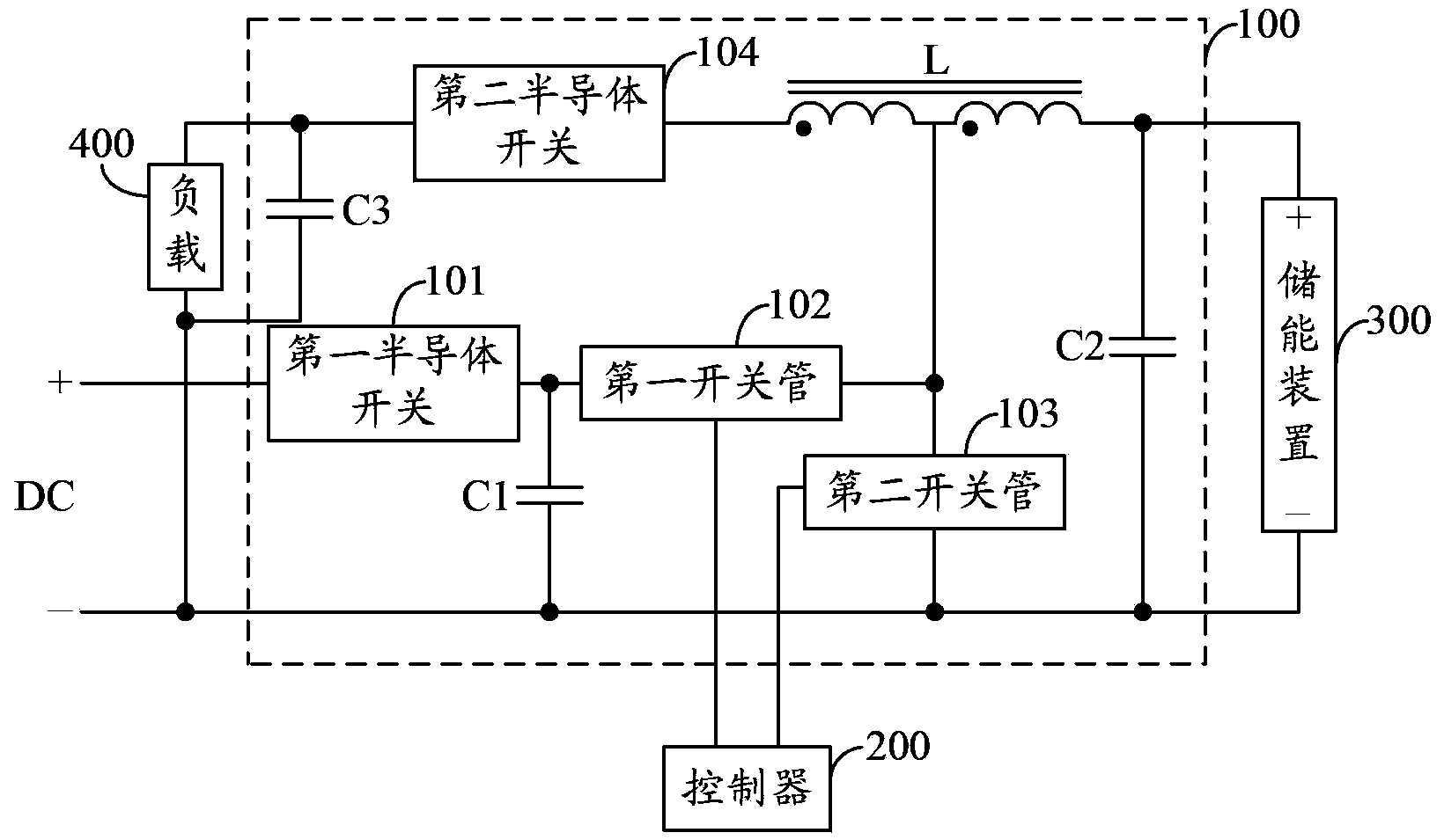
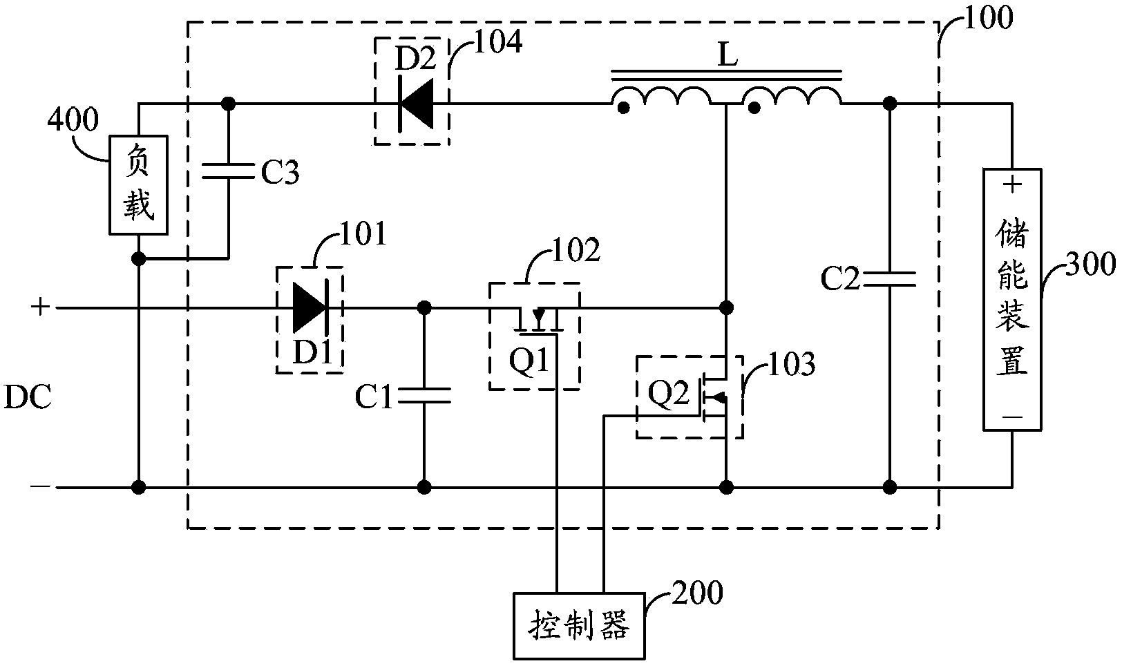
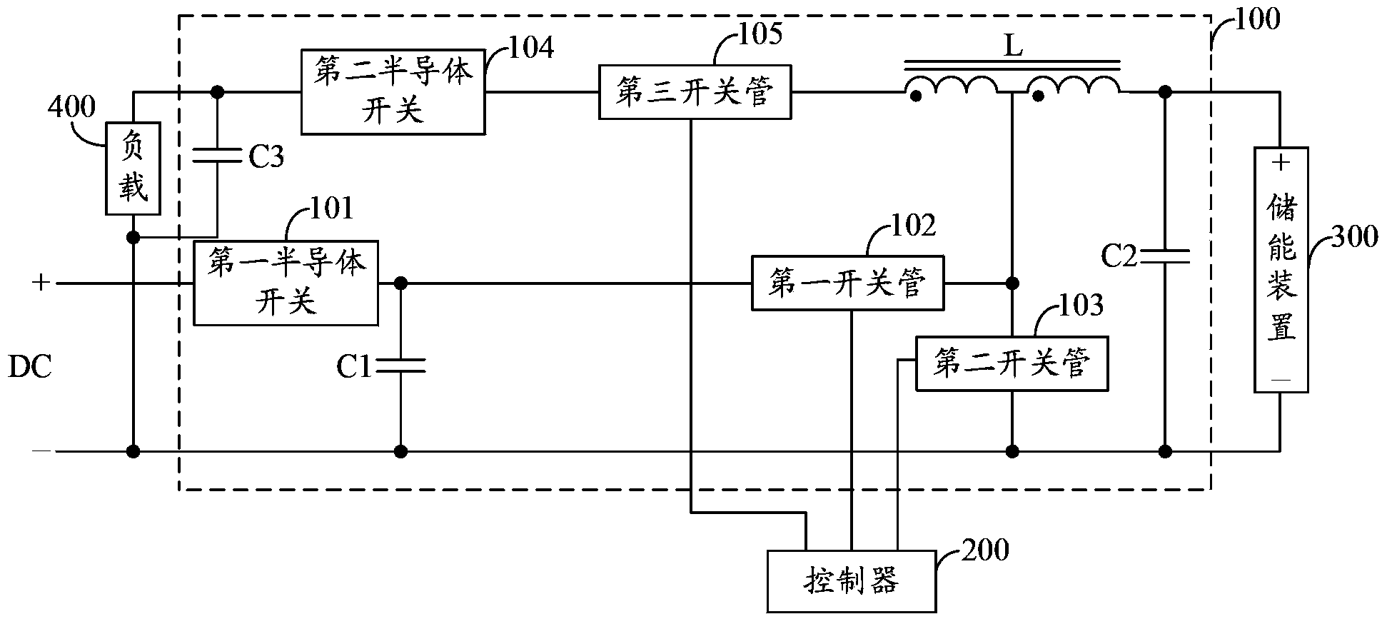
[0016] figure 1 A schematic structural diagram of a charge-discharge DC-DC conversion circuit provided by an embodiment of the present invention is shown. For the convenience of description, only the relevant parts of the present invention are shown, and the details are as follows:

[0017] The charging and discharging DC-DC conversion circuit 100 provided in the embodiment of the present invention is connected to the controller 200, the energy storage device 300 and the load 400, and the charging and discharging DC-DC converting circuit 100 includes:

[0018] A first semiconductor switch 101, a c...


PUM


Abstract

The invention provides a charging and discharging type DC-DC conversion circuit. When an energy storing device is charged, alternate switching-on control is performed on a first switching tube and a second switching tube, the energy storing device is charged by a synchronous ratification BUCK circuit which is composed of a first semi-conductor switching tube, the first switching tube, the second switching tube, a coupled inductor L and a capacitor C2, and meanwhile, a load is powered by a first winding, a second semi-conductor switch and a capacitor C3 of the magnetically integrated coupled inductor L; when the energy storing device is discharged, the anode of the energy storing device outputs DC to supply power to the load through a high-step-up-ratio BOOST circuit which is composed of the coupled inductor L, the second switching tube, the second semi-conductor switch and the capacitor C3, active clamping is performed on the voltage peak produced by the input end of the second switching tube through the first switching tube and the capacitor C1, and electric energy in the capacitor C1 is fed back to the energy storing device for charging when the voltage of the capacitor C1 reaches a preset voltage value, so that the conversion efficiency, the utilization rate and the power density ration of DC are improved, and costs are reduced.

Description

technical field [0001] The invention belongs to the field of electric conversion, and in particular relates to a charge-discharge type DC-DC conversion circuit and a new energy power generation system. Background technique [0002] At present, DC-DC conversion circuits are applied in many fields to provide direct current with a preset voltage for the load, and when charging and discharging functions are required at the same time, the requirements for electrical conversion efficiency are relatively high. For example, in photovoltaic power generation systems, Due to the instability of light and the PV characteristics of photovoltaic modules, it uses a solar maximum power point tracking (MPPT, Maximum Power Point Tracking) controller to detect the power generation voltage of the solar panel in real time, and track the highest voltage and current value, so that The photovoltaic power generation system charges the energy storage device with the highest efficiency. However, due to...

Claims


Application Information

Patent Timeline
IPC IPC(8): H02M3/06H02J15/00H02J7/00
Inventor 马化盛张化伟林宋荣沈世荣
Owner SHENZHEN SED IPD INT ELECTRONICS DEVICE
Why Eureka
Try Eureka