Optical modulator

A technology of optical modulators and optical couplers, which is applied in optics, instruments, nonlinear optics, etc., and can solve problems that affect the transmission degradation of polarization mode dispersion, affect system realizability, and affect modem characteristic requirements, etc.

Active Publication Date: 2013-11-06
NIPPON TELEGRAPH & TELEPHONE CORP
View PDF9 Cites 14 Cited by
  • Summary
  • Abstract
  • Description
  • Claims
  • Application Information

AI Technical Summary

Problems solved by technology

The size of the symbol rate not only affects the size of transmission degradation such as polarization mode dispersion, but also affects the characteristic requirements of the modem, so it becomes an indicator that significantly affects the system implementation

Method used


Image

  • Optical modulator
  • Optical modulator
  • Optical modulator

Examples


no. 1 approach

[0109] [First Embodiment: Basic Concept].

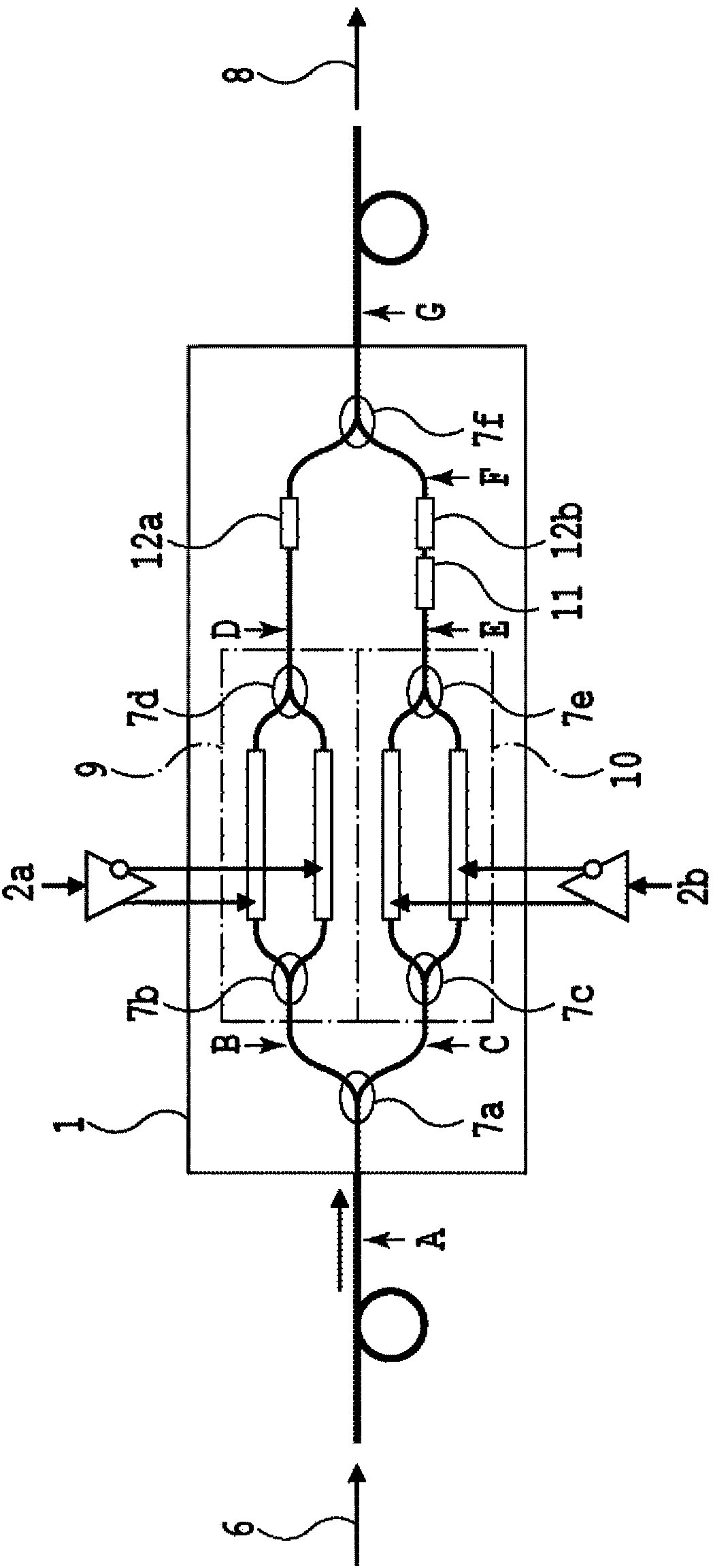
[0110] Figure 7 The structure of the format variable modulator according to the first embodiment of the present invention is shown. The modulator structure of this embodiment consists of a variable 1×M demultiplexing filter 24, M phase modulators (PSK modulators) 13-1~13-4, M / 2 dual-input single-output optical couplers 7a, 7h, and a (M / 2)-input-single-output variable optical coupler 25, wherein the variable 1×M demultiplexing filter 24 is formed by connecting multiple stages of variable 1×2 ILF. Figure 7 An example of M=4 is shown.

[0111] Variable ILF (Tunable ILF: TILF) 27-1-1 to 27-2-2 The optical path length difference ΔL clamped by two 3dB optical couplers 7a-7f (Here, the optical path length difference is not the waveguide length difference, but Considering the refractive index of the waveguide (the value converted to the length in vacuum) of the delay line and the variable optical phase shifter 12a-12f, according to the ...

no. 2 approach

[0133] [Second embodiment: case where M is a power other than 2]

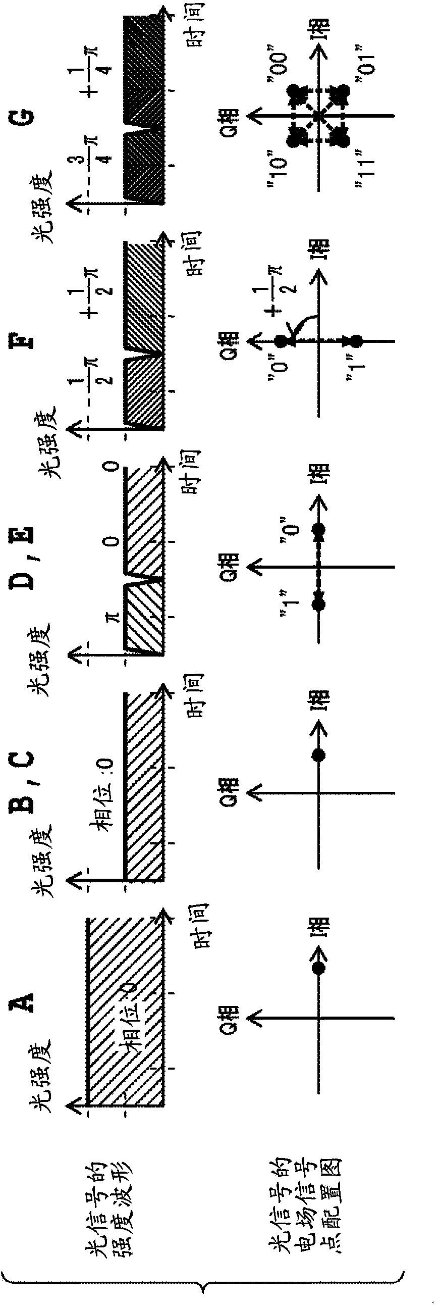
[0134] Next, Figure 14 The configuration when M is not a power of 2, for example, M=12 is shown. This structure is based on the structure of M=16, omitting some structural elements. Specifically, TILF27-4-1~27-4-4 in the fourth section and VC25-4-1~25-4-4 in the first section are respectively arranged in eight in the structure of M=16, while in this In the structure, TILF27-4-1~27-4-4 in the fourth section and VC25-4-1~25-4-4 in the first section are respectively arranged in four. In addition, the structure of the optical modulator array part is also changed from 16 cut down to 12. By reducing a part of the elements of the structure, the number of corresponding carriers can be reduced. Note that, of course, the basic unit ΔL of the difference in optical path length of each TILF in the figure is a value when M=16 by the above formula. Figure 15A and 15B Specific examples of operating states for generatin...

Embodiment 1

[0209] [Format adjustable modulator]

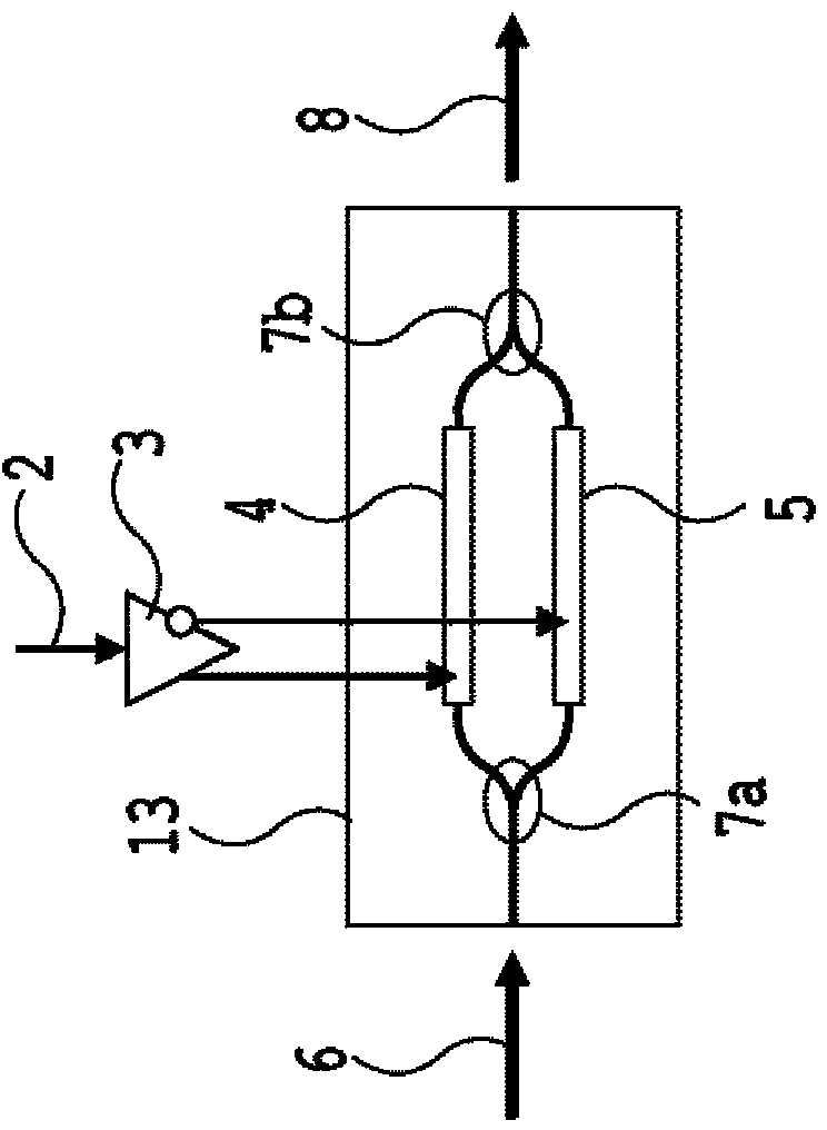
[0210] Figure 33 The structure of the format-tunable modulator fabricated according to the first embodiment is shown. In this embodiment, it is assumed that M=4 in the above-mentioned embodiment, the structure of the distribution part is the pure MZI type of the distribution part type 1, the structure of the collection part is the variable coupler type of the collection part type 1, and the optical modulator array The part takes the nested MZI type QPSK modulator as the basic structure. Therefore, this modulator can be used in three types of modulators: 4-carrier QPSK modulator, dual-carrier 16QAM modulator, and single-carrier 256QAM modulator.

[0211] The modulator is realized by using the composite integration technology (non-patent document 3) after combining the quartz-like planar lightwave circuit (PLC) and the LN modulation array. Because the EO effect is very small, the PLC waveguide cannot constitute a high-speed modulator al...


PUM


Abstract

Provided is an optical modulator that supports a plurality of modulation formats in the same modulator. This optical modulator comprises: a distribution unit comprising an optical demultiplexing / variable optical branching circuit that can switch between an optical demultiplexing function and a branching-ratio variable optical branching function; an optical modulator array connected to the distribution unit; and an aggregation unit connected to the optical modulator array, and comprising a combining-ratio variable combining circuit and / or an optical multiplexing / variable optical combining circuit that can switch between an optical multiplexing function and a combining-ratio variable combining function. The distribution unit forms: a combination of a variable 1×M demultiplexer / brancher, one or a plurality of fixed interleave filters, and an optical switch; and / or a combination of a plurality of variable optical couplers, and an optical switch. The optical modulator array comprises a plurality of optical modulators. The aggregation unit comprises a configuration from: a combination of one or a plurality of variable optical couplers, and a plurality of variable attenuators; and / or a combination of an M×1 variable coupler, a variable M×1 demultiplexer / brancher, one or a plurality of fixed interleave filters, and an optical switch.

Description

technical field [0001] The present invention relates to an optical modulator, and more particularly, to an optical modulator capable of changing the combination of the number of carriers and the number of modulation stages of a modulated signal. Background technique [0002] Now, the 100Gs transmission system is gradually being put into practical use in the optical fiber communication system. In the 100Gs transmission system, Quadrature Phase-Shift Keying (OPSK modulation) method and complex Using polarization multiplexing, one of the technologies, to achieve a high transmission rate of 128Gbps per channel. Multi-level modulation technology is a technology that uses the amplitude and phase information of an optical signal to transmit multiple information in one symbol. In the QPSK modulation scheme, 2-bit information is transmitted with one symbol by assigning symbols to four stages, that is, four phase states. Polarization multiplexing is a technology that uses polarizati...

Claims


Application Information

Patent Timeline
Patent Type & Authority Applications(China)
IPC IPC(8): G02F1/01
CPCH04B10/5053H04B10/5161G02F1/0115G02F1/2255
Inventor 乡隆司山崎裕史
Owner NIPPON TELEGRAPH & TELEPHONE CORP
Why Eureka
Try Eureka