
Temporary storage and mixing system used for material, and application method thereof

A mixing system and material technology, applied in the field of temporary storage and mixing systems of food materials, can solve the problems of difficult management, easy pollution, high error rate, etc., and achieve the effects of good airtightness, reduced pollution sources, and low equipment failure rate

Inactive Publication Date: 2013-11-13
上海博正名荣包装机有限公司
View PDF0 Cites 9 Cited by
  • Summary
  • Abstract
  • Description
  • Claims
  • Application Information

AI Technical Summary

Problems solved by technology

[0004] The purpose of the present invention is to provide a temporary storage and mixing system for materials, which can overcome the separation of material mixing and temporary storage equipment in the prior art, which is easy to cause pollution when mixing, cumbersome work and difficult management when mixing different products , some shortcomings of high error rate

Method used


Image

  • Temporary storage and mixing system used for material, and application method thereof
  • Temporary storage and mixing system used for material, and application method thereof

Examples


Embodiment 1

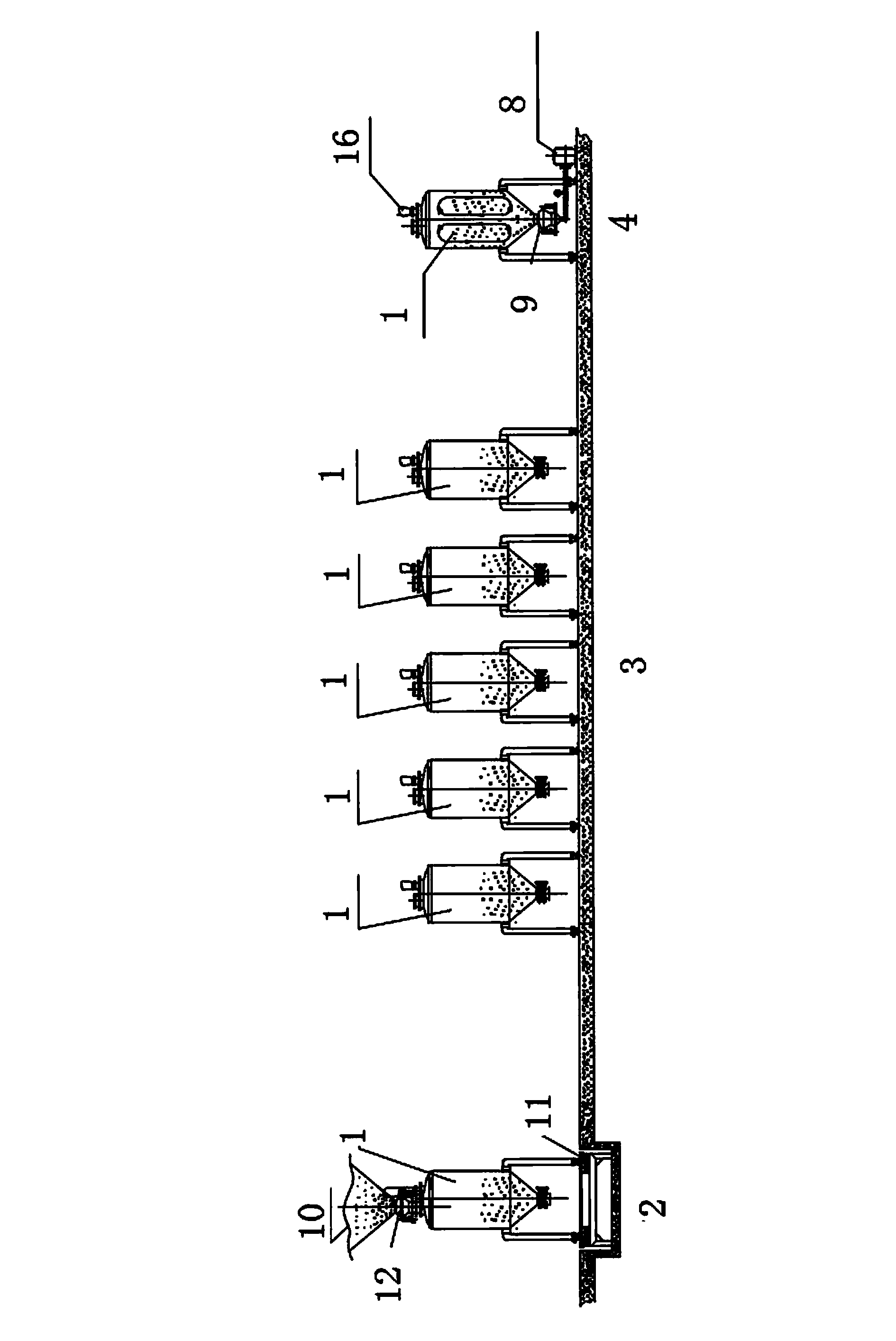
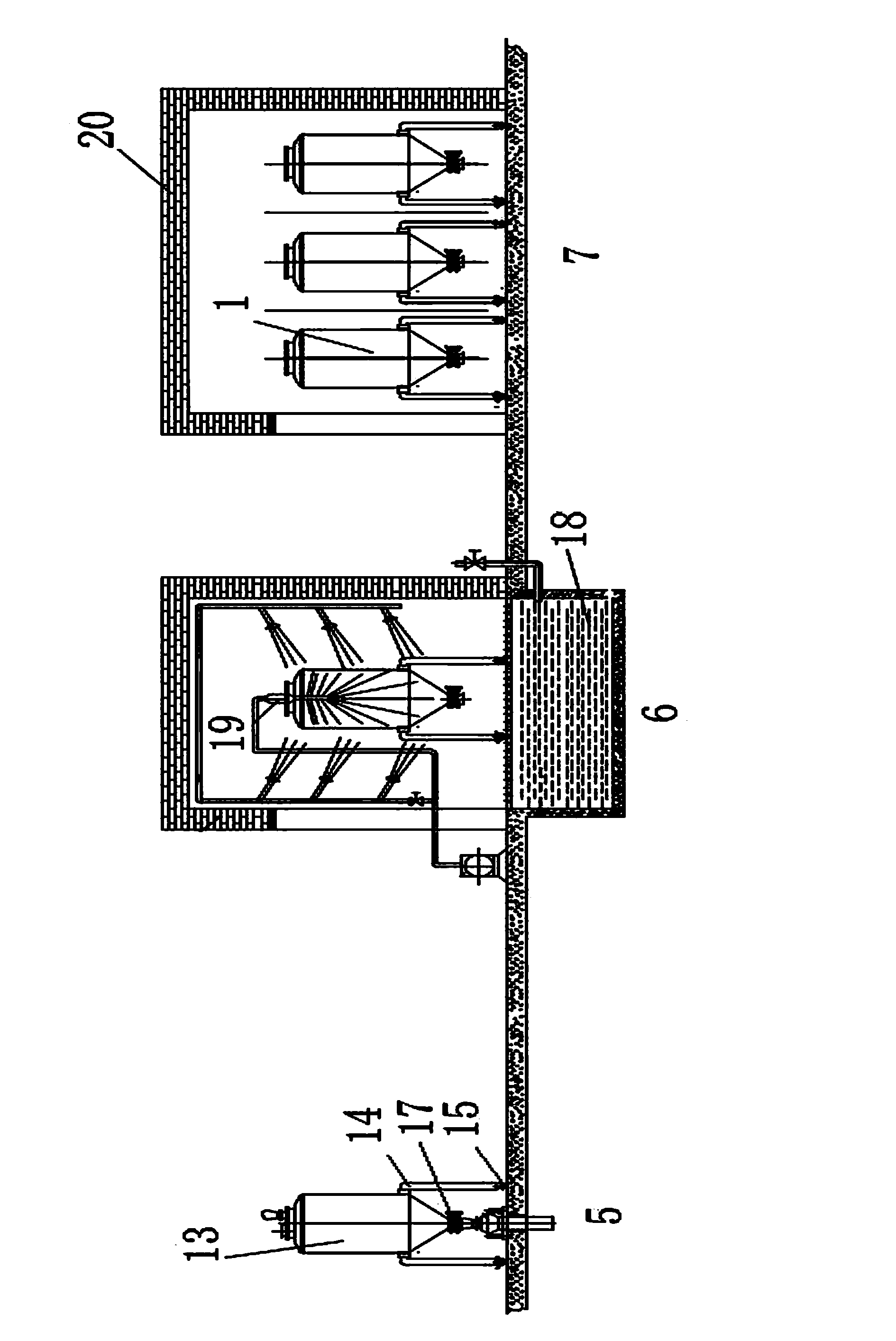
[0023] The material temporary storage container is equipped with at least one powder bin body, which is made of stainless steel. The volume of the powder bin body is 1 cubic meter. The lower part is conical, and the lower end has a discharge port and a gas injection structure, and a butterfly valve is provided on the discharge port. Wheels are arranged at the bottom of the powder bin body, which can move among various stations of the present invention, such as feeding, mixing, discharging, and cleaning. When the material temporary storage container moves to the feeding station, the material can be directly fed into the powder bin body through the feeding hopper. A weighing device is installed under the working position platform of the feeding station, which has weight for the powder bin body moved above it. The weighing function can set the weight of the material added to the powder bin according to the processing requirements. When the material temporary storage container mo...

Embodiment 2

[0025] At the feeding station, materials are injected into the material temporary storage container, but the feeding is stopped after the weight of the material reaches the set amount. After the feeding is stopped, the material temporary storage container that will not be mixed for the time being can be moved to the storage station for storage. The material temporary storage container for mixing processing is moved to the mixing station. According to the formula requirements, ingredients can be put in here. If there is no ingredient, directly connect the high-pressure air compressor to the material temporary storage container, and inject clean, The dry and cold air makes the materials empty and flip in the material temporary storage container until they are uniformly mixed; then the material temporary storage container is moved to the discharge station, and the butterfly valve at the discharge port is opened, so that the mixed material can be directly mixed. Supply packaging ma...


PUM


Abstract

The invention relates to a temporary storage and mixing system used for materials, and an application method thereof. The system is characterized in that: the material temporary storage and mixing system is provided with a feeding station and a mixing station which are respectively provided with a feeding device and a mixing device matching a material temporary storage container. When in use, functions such as feeding, storing, and mixing can be completed in a same material temporary storage container. During mixing, the system is directly connected with a high-pressure air machine through an air injection structure on the bottom of the material temporary storage container; clean high-pressure air is injected into the material temporary storage container; the material is lifted and turned under the driving of air, such that a purpose of uniform mixing is achieved. Also, secondary pollution during material temporary storage and mixing is reduced. The operation of the entire mixing process is convenient and less error-prone.

Description

technical field [0001] The invention relates to the technical field of the food industry, in particular to a temporary storage and mixing system for food materials and its application method. Background technique [0002] The usual practice in the food industry has been that the mixing and temporary storage equipment for materials are two separate equipments, and these different equipments complete their respective functions, but when materials need to be mixed, the materials must be removed from the temporary storage equipment. Inject into the mixing equipment; however, when temporary storage is required, the material must be injected into the temporary storage equipment. The above-mentioned injection process is likely to cause bacterial contamination. At the same time, the mixing equipment and the temporary storage equipment need to be cleaned separately, which is time-consuming and labor-intensive. [0003] If the formula changes frequently, multiple mixers are needed to ...

Claims


Application Information

Patent Timeline
Patent Type & Authority Applications(China)
IPC IPC(8): B01F13/02B01F15/00B01F15/02B01F33/40
Inventor 王纯立
Owner 上海博正名荣包装机有限公司
Learn More