Thin steel wire cooling processing device and method

A technology of cooling device and thin steel wire, applied in heat treatment furnaces, heat treatment equipment, furnaces, etc., can solve the problems of high production consumption, high energy consumption, large production investment, etc., and achieve uniform core and surface temperature, simple process, high quality stable effect

Inactive Publication Date: 2013-11-20
ZHANGJIAGANG SHENGDA STEEL ROPE
View PDF2 Cites 0 Cited by
  • Summary
  • Abstract
  • Description
  • Claims
  • Application Information

AI Technical Summary

Problems solved by technology

Secondly, the production investment is large, and a lead tank uses about 50 tons of lead
Third, the production consumption is large
Fourth, energy consumption is high
Due to the inhomogeneity of the local water temperature in the water tank, the cooling of each steel wire is not uniform, so the heat treatment performance of the steel wire using this water bath cooling method is unstable and cannot be industrialized.
[0004] A quenching and cooling device for steel wire and steel rod with publication number CN201367452 has the defect that the process cooling capacity cannot be continuously adjusted online, and the cooling capacity is uncontrollable
Moreover, only the rapid supercooling stage of steel wire water quenching cooling is considered, and the inconsistency between the core temperature and surface temperature of the steel wire due to rapid cooling is not considered. After the steel wire passes through the cooler for a few seconds, the temperature rises by tens of degrees, and even reaches the embrittlement zone. , resulting in unstable heat treatment quality of steel wire

Method used


Image

  • Thin steel wire cooling processing device and method
  • Thin steel wire cooling processing device and method
  • Thin steel wire cooling processing device and method

Examples


Embodiment Construction

[0047] Specific embodiments of the present invention will be described below in conjunction with the accompanying drawings.

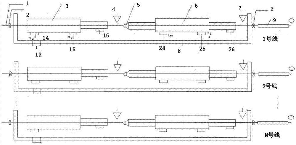
[0048] figure 1 It is a schematic diagram of the composition of the thin steel wire vaporization cooling treatment device of the present invention. The device is composed of a guide wheel 2, a primary vaporization chamber 3, a primary infrared thermometer 4, a nozzle 5, a secondary vaporization chamber 6, a secondary infrared thermometer 7, a heat preservation chamber 9 and other devices connected in sequence.

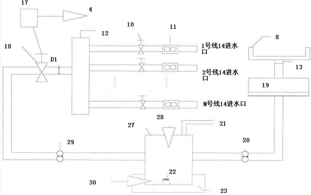
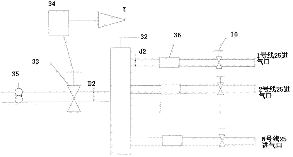
[0049] The vaporization chamber has a water inlet and an air inlet, by adjusting the water flow V in the water inlet w In proportion to the intake air flow Vq in the intake port, water vapor with different cooling capacities can be obtained. When V w =0, what is injected is compressed air, and its cooling ability is the weakest; when Vq=0, what is injected is compressed water, and its cooling ability is the strongest. When the ratio of water...


PUM


Abstract

The invention discloses a thin steel wire cooling processing method for a thin steel wire heating processing technology. The method comprises the following steps of: performing splat cooling on thin steel wires to be cooled through a first-class vaporizing chamber, wherein cooling tendering is avoided; measuring the temperatures of the thin steel wires after the splat cooling by using a provided first-class infrared thermometer so as to enable the thin steel wires to be subjected to slow cooling and balancing the temperatures of the core parts and the surfaces of the thin steel wires; measuring the temperatures of the thin steel wires after slow cooling by using a provided second-class infrared thermometer; preserving the steel wires which are cooled to the target temperature by using a provided temperature supply and preservation chamber so as to enable the metallographic phases of the thin steel wire to be fully changed collecting cooling water by using a provided water supplying groove so as to enable the cooling water to be recycled, wherein thermostatted water the temperature of which is 30 DEG C+ / -1DEG C is utilized as a cooling liquid after ultrasonic vaporization, and enters the first-class vaporizing chamber and the second-class vaporizing chamber to cool the steel wires.

Description

technical field [0001] The invention relates to a method and device for heat treatment of steel wire, especially a method and device for cooling treatment of thin steel wire. Background technique [0002] At present, the intermediate heat treatment and final heat treatment of domestic medium-carbon steel wire and high-carbon steel wire are widely used in the traditional process of high-temperature air normalizing and high-temperature lead quenching. In production, after heating, dozens of steel wires are very close to each other and pass side by side over or inside the lead tank with a temperature of about 500°C for air normalizing or high-temperature lead quenching. The only advantage of this process is that the production is stable and it is relatively easy to ensure the mechanical properties of the finished steel wire. But its shortcoming is many, and quite serious. For example, causing environmental pollution. The melting point of lead is 327°C, and lead melt at 500°C...

Claims


Application Information

Patent Timeline
IPC IPC(8): C21D9/52
Inventor 陆海徐一铭
Owner ZHANGJIAGANG SHENGDA STEEL ROPE
Why Eureka
Try Eureka