Potable liquid sampling device and liquid sampling method
A liquid sampling and sampling device technology, applied in the direction of sampling devices, etc., can solve the problems of limited sampling, full-level liquid samples cannot be sampled at one time, and liquid samples are not easy to pour out, etc., to achieve accurate and convenient sampling, convenient and fast sampling , The effect of shortening the sampling time
- Summary
- Abstract
- Description
- Claims
- Application Information
AI Technical Summary
Problems solved by technology
Method used
Image
Examples
Embodiment 1
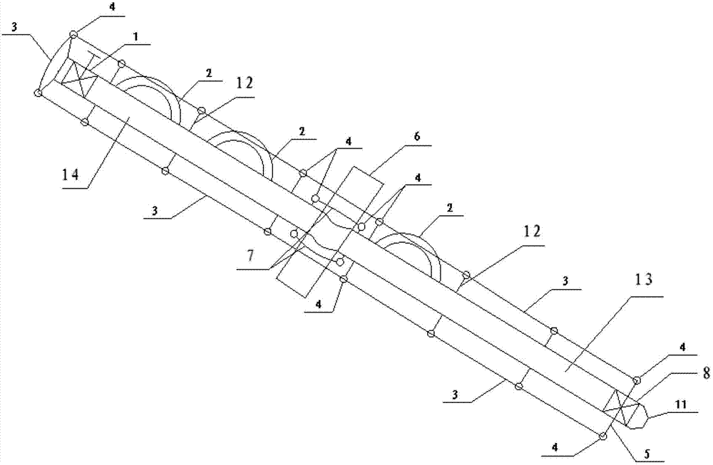
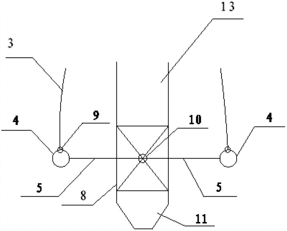
[0040] A portable liquid sampling device, the structure of which is figure 1 , figure 2 As shown, including sampling pipe and steel wire rope 3, the sampling pipe is a pipe body with openings at both ends, the sampling pipe is a DN25 stainless steel pipe, the length of the pipe body is 10m, and a bottom ball valve 8 is arranged at the bottom of the pipe body. The end ball valve 8 comprises a ball valve body, a ball valve core, a ball core shaft 10 and a bottom ball valve handle 5. One end of the ball core shaft 10 is fixedly connected to the ball valve core, and the other end is connected to the middle part of the bottom ball valve handle 5; There is a top ball valve 1 at the top of the tube, a scale line is set on the outer wall of the sampling tube between the top ball valve 1 and the bottom ball valve 8, and two rows of opposite rope-threading guide rails are set on the outer wall of the pipe body. The guide rail includes several spaced stringing rings 4, and each stringi...
Embodiment 2
[0046] With the liquid sampling device described in embodiment 1, the difference is:
[0047] The sampling pipe is a DN25 stainless steel pipe, the length of the pipe body is 15m, and the horizontal distance between two rows of relative rope guide rails is 15cm. There are 4 semicircular sampler handles 2.
Embodiment 3
[0049] With the liquid sampling device described in embodiment 1, the difference is:
[0050] The sampling tube is divided into a first sampling tube 13 and a second sampling tube 14, the bottom ball valve 8 is arranged on the bottom of the first sampling tube 13, and the top of the first sampling tube 13 is connected with the second sampling tube 14 by a quick connector 6, The top ball valve 1 is arranged on the top of the second sampling tube 14 . A joint connecting rope 7 is arranged at the junction of the first sampling pipe and the second sampling pipe. Thread the rope between the rings. When not in use, the two sampling tubes are connected together by the joint connecting rope, which is convenient to fold the two sampling tubes together, occupies a small area, saves space, and is easy to carry and move. The sample tubes are connected together. structured as figure 1 shown.
PUM
 Abstract
Description
Claims
Application Information
 - R&D
- Intellectual Property
- Life Sciences
- Materials
- Tech Scout
- Unparalleled Data Quality
- Higher Quality Content
- 60% Fewer Hallucinations
Browse by: Latest US Patents, China's latest patents, Technical Efficacy Thesaurus, Application Domain, Technology Topic, Popular Technical Reports.
© 2025 PatSnap. All rights reserved.Legal|Privacy policy|Modern Slavery Act Transparency Statement|Sitemap|About US| Contact US: help@patsnap.com


