Large-viewing-field and high-precision star sensor optical system

A technology of star sensor and optical system, which is applied in the optical field to achieve the effect of increasing the relative aperture, small absorption and shortening the total length of the system

Inactive Publication Date: 2013-11-20
HARBIN INST OF TECH
View PDF3 Cites 15 Cited by
  • Summary
  • Abstract
  • Description
  • Claims
  • Application Information

AI Technical Summary

Problems solved by technology

[0011] The purpose of the present invention is to solve the problems existing in the existing star sensor optical system and provide a star sensor optical system with a large field of view and high precision

Method used


Image

  • Large-viewing-field and high-precision star sensor optical system
  • Large-viewing-field and high-precision star sensor optical system
  • Large-viewing-field and high-precision star sensor optical system

Examples


specific Embodiment approach 1

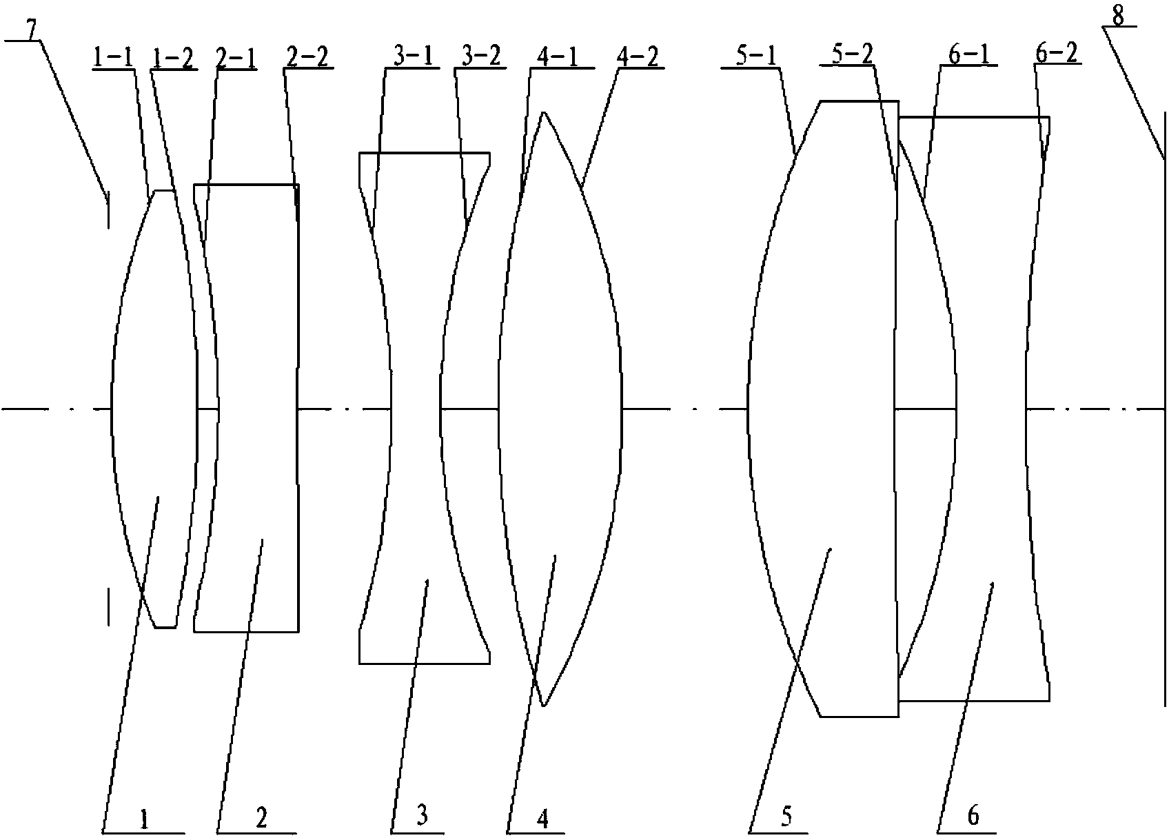
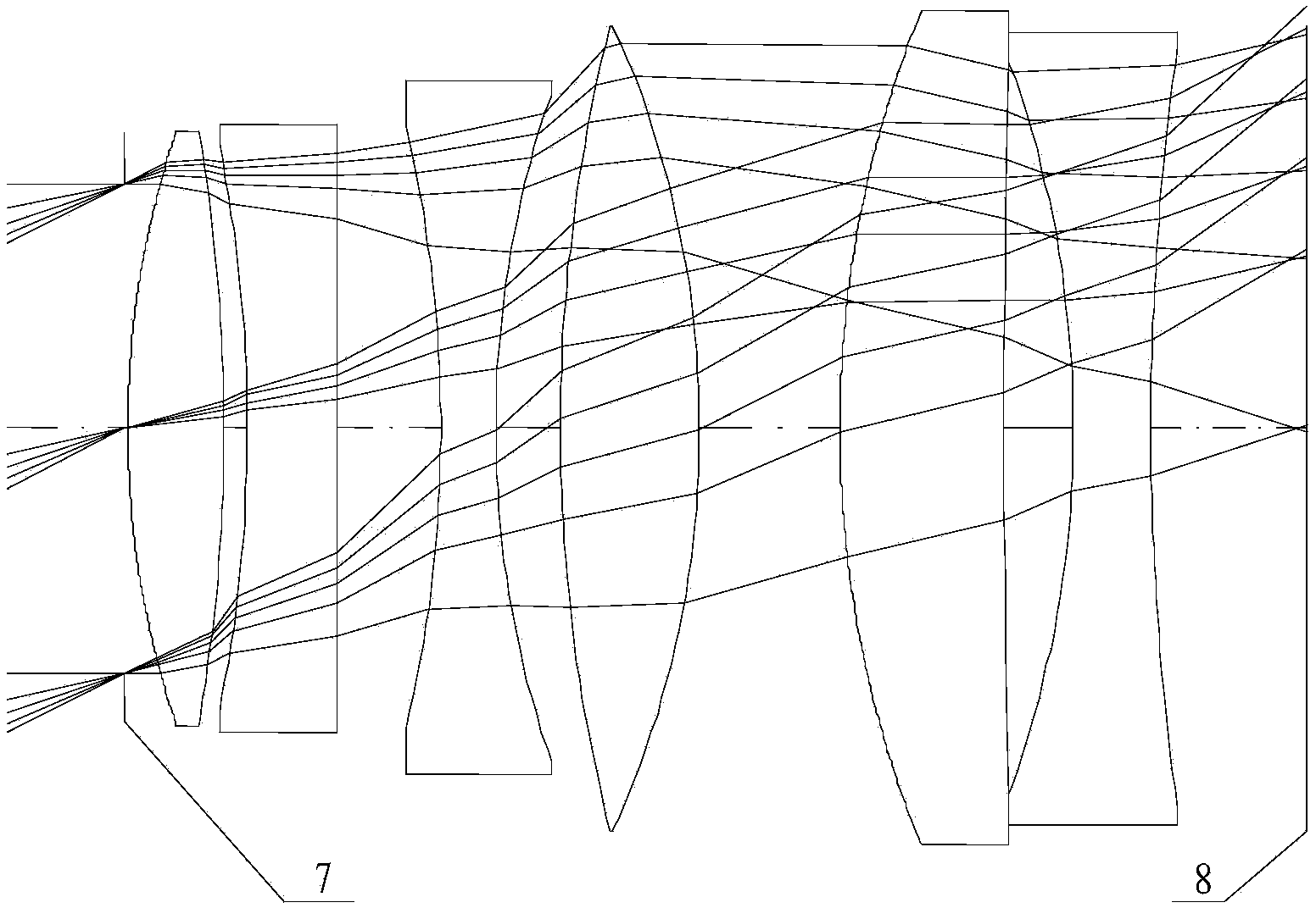
[0024] Specific implementation mode one: the following combination Figure 1 to Figure 7 Describe this embodiment mode, a kind of high-precision star sensor optical system of large field of view described in this embodiment mode, it comprises diaphragm 7, lens group and image plane 8, the light that the star sends in the field of view enters through diaphragm 7 to The lens group, after being transmitted by the lens group, forms an image on the image plane 8;

[0025] The lens group is a near image telecentric optical system composed of the first lens 1, the second lens 2, the third lens 3, the fourth lens 4, the fifth lens 5 and the sixth lens 6;

[0026] The first lens 1, the second lens 2, the third lens 3, the fourth lens 4, the fifth lens 5 and the sixth lens 6 are sequentially placed on the same optical axis according to the direction from the diaphragm 7 to the image plane 8;

[0027] The first lens 1, the fourth lens 4 and the fifth lens 5 are positive lenses, and the ...

specific Embodiment approach 2

[0034] Specific embodiment two: this embodiment is described further to embodiment one, the mirror surface of each eyeglass in the set lens group facing the diaphragm 7 is the first mirror surface, and the mirror surface facing the image plane 8 is the second mirror surface, then the mirror surface of the lens group Each mirror surface is the first mirror surface 1-1 of the first lens 1, the second mirror surface 1-2 of the first lens 1, the first mirror surface 2-1 of the second lens 2, and the second mirror surface 2-2 of the second lens 2 , the first mirror surface 3-1 of the third lens 3, the second mirror surface 3-2 of the third lens 3, the first mirror surface 4-1 of the fourth lens 4, the second mirror surface 4-2 of the fourth lens 4, the second mirror surface 4-2 of the fourth lens 4 The first mirror surface 5-1 of the fifth mirror 5, the second mirror surface 5-2 of the fifth mirror 5, the first mirror surface 6-1 of the sixth mirror 6 and the second mirror surface 6...

specific Embodiment approach 3

[0036] Specific embodiment three: this embodiment will further explain embodiment two, the positional relationship of each lens in the lens group, and the radius of curvature of each lens are selected according to the following table:

[0037]

[0038] The distance between the second mirror surface 6-2 of the sixth lens 6 and the next mirror surface along the central axis in the above table refers to the distance between the second mirror surface 6-2 of the sixth lens 6 and the image plane 8 along the central axis in the table.


PUM


Abstract

The invention discloses a large-viewing-field and high-precision star sensor optical system, belongs to the field of optics, and aims to solve the problems of a conventional star sensor optical system. The system comprises a diaphragm, a lens group and an image plane, wherein light rays emitted by fixed stars in the viewing field go into the lens group through the diaphragm, and are imaged on the image plane after transmitted by the lens group; the lens group is a near image space telecentric optical system consisting of a first lens, a second lens, a third lens, a fourth lens, a fifth lens and a sixth lens; the first lens, the second lens, the third lens, the fourth lens, the fifth lens and the sixth lens are sequentially placed on the same optical axis in a direction from the diaphragm to the image plane; and the first lens, the fourth lens and the fifth lens are positive lenses, and the second lens, the third lens and the sixth lens are negative lenses.

Description

technical field [0001] The invention relates to a star sensor optical system with large field of view and high precision, which belongs to the field of optics. Background technique [0002] The star sensor is an attitude sensor with high measurement accuracy in the aircraft control system, and plays a particularly important role in the attitude control of the satellite. In recent years, with the rapid development of micro-satellite technology, especially the increasingly extensive research and application of autonomous navigation star sensors, star sensors have gradually developed towards the trend of large field of view, light weight, and high precision. [0003] At present, the key technologies of star sensors mainly include optical system development technology, image processing technology, star map matching, etc. Among them, the design of the optical system is an important part in the development process of the star sensor. Due to the different imaging targets and the r...

Claims


Application Information

Patent Timeline
Patent Type & Authority Applications(China)
IPC IPC(8): G02B13/22G02B13/00G02B13/18G02B1/00
Inventor 耿云海王爽孙亚辉
Owner HARBIN INST OF TECH
Why Eureka
Try Eureka