
Laser broadband cladding device and method

A laser and cladding technology, applied in laser welding equipment, optics, optical components, etc., can solve the problems of weak spot light intensity, small molten pool, fast heat dissipation, etc., to achieve accurate coupling, uniform temperature distribution, and high processing efficiency. Effect

Active Publication Date: 2013-11-20
SUZHOU UNIV
View PDF7 Cites 27 Cited by
  • Summary
  • Abstract
  • Description
  • Claims
  • Application Information

AI Technical Summary

Problems solved by technology

[0003] (1) The powder beam is obliquely sent into the beam from the outside of the laser beam. The powder beam interferes with the laser beam in the air before falling into the spot, resulting in absorption and diffuse reflection, which weakens the light intensity of the spot on the processing surface. The smoothness of the melting channel is not good, and the internal defects increase
[0004] (2) Powders of different particle sizes and shapes are affected by fluctuations in parameters such as fluidity, powder feeding volume and uniformity in each powder pipe. Due to the influence of loading pressure, gravity, etc., plus the effect of protective gas and light pressure, the powder particles fall in a parabolic shape, and the inertia, movement trajectory and landing point of each powder particle will be inconsistent, which will cause the particle drop area to become larger and fluctuate.
For the double-sided powder feeding scheme, the position of the powder beams, the error of the average powder amount, the uniformity of the spraying force, and the symmetry are not consistent, and the convergence accuracy is difficult to stabilize.
During the movement of powder particles, some powder particles fall into the light spot, but the density distribution after entering the beam is uneven; Connected to the melting channel next to the molten pool, causing a lot of waste of powder and environmental pollution
[0005] (3) In the existing broadband cladding method, the energy of the spot is generally uniformly distributed, and the heat dissipation is faster on both sides of the melting channel during forming, resulting in insufficient energy here, resulting in poor boundary fusion and affecting the quality of the melting channel lap
However, the current internal powder feeding scheme focuses on a circular spot, the molten pool is small, and the one-time scanning area is narrow, and the cladding efficiency is limited, so it cannot be applied to broadband cladding.

Method used


Image

  • Laser broadband cladding device and method
  • Laser broadband cladding device and method
  • Laser broadband cladding device and method

Examples


Embodiment Construction

[0046] The technical solutions in the embodiments of the present invention will be clearly and completely described below in conjunction with the accompanying drawings in the embodiments of the present invention. Obviously, the described embodiments are only some of the embodiments of the present invention, not all of them. Based on the embodiments of the present invention, all other embodiments obtained by persons of ordinary skill in the art without making creative efforts shall fall within the protection scope of the present invention.

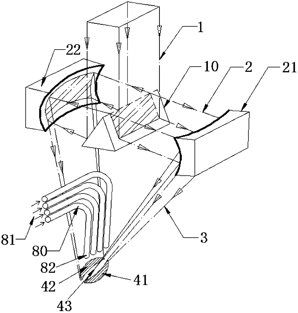
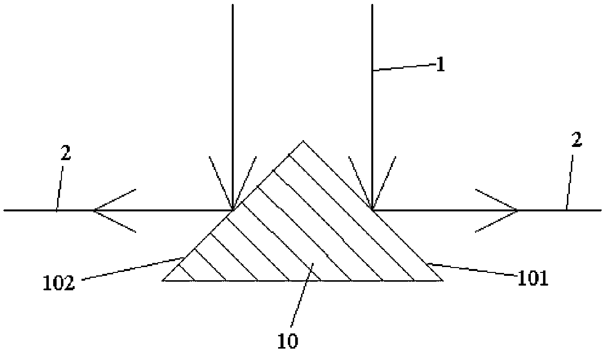
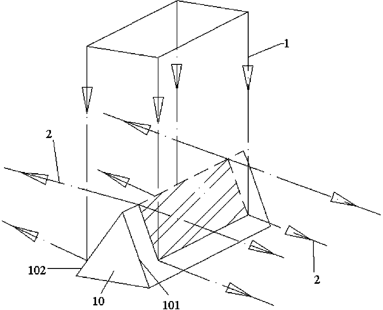
[0047] The laser broadband cladding device of the present invention is mainly composed of a beam splitting prism and a condenser mirror. The beam-splitting prism is composed of two beam-splitting planes that are symmetrically arranged and intersect at a certain angle. The two beam-splitting planes can symmetrically reflect the incident solid laser beam into two reverse laser beams; The two beam-splitting surfaces of the prism are arranged o...


PUM


Abstract

The invention discloses a laser broadband cladding device and method. The device mainly consists a beam splitter prism and two converging lenses, wherein the beam splitter prism is formed into a molded surface by two beam splitter planes which are symmetrically arranged and are intersected at a certain angle; an incident solid laser beam can be symmetrically reflected by the two beam splitter planes to form two reverse emergent laser beams; the two converging lenses are respectively opposite to the two beam splitter surfaces of the beam splitter prism; two beams of laser reflected by the beam splitter prism can be respectively reflected into parallel near rectangular laser beams by the converging lenses; the distance between the two beams of parallel near rectangular light is shorter and shorter in the focusing process to form long and narrow focusing light spots; and the light spots are overlapped on a focal plane. The laser broadband cladding device disclosed by the invention has the advantages of big cladding width and high efficiency, a powder bundle does not interfere with a light beam too early in the falling process, and the light beam has a small reflection loss; the powder enters the light in an accurate, straight, thin and stiff way, is evenly distributed and has the advantages of small diffusance and high use ratio; the coupling precision of the powder and the laser beam is high; turnaround scanning forming can be realized; a cladding channel has even tissue; the overlapping joint quality is good.

Description

technical field [0001] The invention relates to the technical field of laser cladding processing, in particular to a laser broadband cladding device and method. Background technique [0002] Laser cladding, that is, the use of high-energy laser beams to melt metal materials and produce metallurgical bonds with matrix materials, is widely used for surface strengthening, repairing and modification of materials. For some large workpieces, such as the surface of large shaft parts, large-area plane laser cladding, etc., the wide-band laser scanning can scan a large area at a time, which can greatly improve the cladding efficiency, and improve the cladding efficiency due to the reduction of the number of laps. cladding quality. The existing laser broadband cladding method is as follows: the laser beam generated by the laser is converted into a narrow and long focused spot by means of an integrator mirror, etc., and irradiated to the surface to be processed to form a molten pool, ...

Claims


Application Information

Patent Timeline
Patent Type & Authority Applications(China)
IPC IPC(8): G02B27/09C23C24/10G02B27/10
CPCB23K26/0608B23K26/0676B23K26/0738B23K26/144B23K26/34
Inventor 石世宏傅戈雁雷定中
Owner SUZHOU UNIV
Learn More